

Hi, friends, long time no see. Here is ZMotion.

Our technical support on "EtherCAT Motion Controller" is back, and today bring our the last part "EtherCAT Bus Quick Start".
Mainly, it will showhow to control EtherCAT bus drive for EtherCAT bus motion controller, here we take XPLC006E multi-axis economical EtherCAT bus motion controller as the example. Specifically, there are 5 parts,hardware wiring method, communication between controller and EtherCAT bus drive, EtherCAT bus drive related parameters configuration, EtherCAT bus initialization and motion control after initialized.
--XPLC006E Function Introduction--

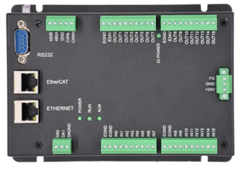
XPLC006E
is a kind of multi-axis economical EtherCAT bus motion controller developed by ZMotion Technology, and XPLC series motion controllers can be applied in all kinds of occasions that need offline or online operation.

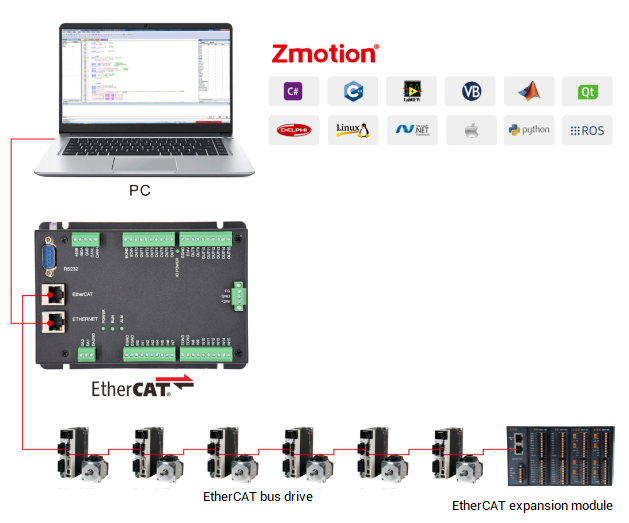
XPLC006E has 6 motor axes itself, and motion control of 12 axes at most can be achieved (including virtual axes). Also, it supports 12-axis linear interpolation, electronic cam, electronic gear, synchronous follow, virtual axis setting, etc.
In addition, XPLC006E cost-effective controller supports multi-task run synchronously. At the same time, it can do simulation on PC directly. There are several valid programming methods, such as, Basic / PLC ladder diagram / HMI configuration in ZDevelop software and commonly used upper computer software.
For PC upper computer API programming, following interfaces are supported: C#, C++, LabVIEW, VB, matlab, Qt, Linux, .Net, iMAC, Python, ROS, etc.

--XPLC864E2 Function Introduction--

Let's see
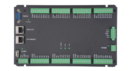
XPLC864E2
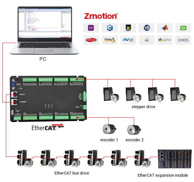
, it is upgraded on the basis of XPLC006E, which means, it supports all functions of XPLC006E mentioned above, and usages are basically the same. However, some resource spaces are better than XPLC006E. What's more, XPLC864E2 supports 32 inputs, 32 outputs, 2 ADs and 2 DAs in hardware level, pulse axis and bus axis can be hybrid used. The number of real axes is 8 totally. Except EtherCAT interface, in hardware of output, signal output of 8 axes in pulse direction can be configured, and be with 2 encoder inputs set by input configuration.
Same, XPLC864E2 supports PLC, Basic and HMI configuration programming methods. For PC upper computer API programming, following interfaces are supported: C#, C++, LabVIEW, VB, matlab, Qt, Linux, .Net, iMAC, Python, ROS, etc.


1. Communication Wiring
Use one cable to connect "EtherCAT Bus Port" of XPLC006E controller to "EtherCAT Bus Port" of servo driver.
Note: there are two EtherCAT interfaces of the servo drive. These two ports can be connected with some drivers at will, but some drives are divided into "EtherCAT IN" and "EtherCAT OUT". The IN port is connected to the upper-level device, and the OUT port is connected to the next-level device. They cannot be mixed, pay attention to the connection sequence.
In the case of multi-axis control, the EtherCAT OUT port of the servo drive is connected to the EtherCAT IN port of the next-level drive device, and so on.
The rules for slot number, node number and drive number are shown in the figure above. The slot number of the EtherCAT bus interface is 0 by default, and the node numbers are numbered sequentially from 0 according to the connection sequence with the controller. Device numbers with motors are ignored for other types of devices. They are also numbered from 0 according to the connection sequence. These numbers will be used in bus instructions.
After the hardware wiring is completed, it is necessary to run the bus initialization program to communicate with the driver. See the initialization template program below.
Note: When using the EtherCAT bus expansion module, the bus initialization operation must also be performed, and the expansion IO can only be operated after mapping the IO number.
Connect controller to computer through serial port or net port. Below introduces net port connection.
It is recommended to use twisted pair cable with shield layer for good quality of communication. Firstly, use one cable line to connect them, and power on the controller. Then, open ZDevelop. In menu bar, click “Controller” – “Connect”, open the window like the below figure.

Through this window, native IP can be viewed rapidly, and check whether they are in the same net segment.
When selecting the IP from the list, valid IP addresses within the current LAN will be found automatically (when POWER and RUN lights, IP address of this controller can be checked).
When there are multiple controllers in the same network, if the IP drop-down list does not display the IP address of the target controller, you can use an IP scan to view all currently available controller IP addresses. After the scan is complete, make sure to close this window and restart the IP drop-down list selection.

After selecting the correct IP address and clicking "Connect", there will be a message prompting whether the connection succeeds or fails.
The controller factory IP is 192.168.0.11, the "Connect to Controller" window can display the local IP address, please pay attention to set the respective IPs of the wire d network card and the wireless network card. And controller IP address and computer IP address must be the same network segment, which means first three segments are the same and the last segment is different. Otherwise, it will fail to connect, for this situation, modifying controller IP or computer IP.
If the controller IP address is forgotten, you can connect to the controller through the network port, and then obtain the controller IP.
2. Drive PDO Setting
The PDO of the drive is a necessary configuration, which represents the functions contained in the current drive.
The full name of PDO is Process Data Object, which refers to the function of periodically exchanging data between the master station and the slave station in the EtherCAT bus network. It can be regarded as an array space, and each array element stores a different function code. PDO executes the operations corresponding to these function codes in one cycle. These function codes are called data dictionaries, and the data dictionaries are represented by 4-digit hexadecimal numbers.

PxPDO: data is transferred to slave station from master station
TxPDO: data is transferred to master station from slave station
The controller in EtherCAT bus is master station, the servo drive is slave station.
For example, 6040h control word (used to control some running status of servo axis, such as, enable, on, off, alarm, reset, etc), and each data dictionary Index can include 32 sub-dictionary "Sub-Index". For functions and initial values of data dictionary, please refer to drive manual.
The number and function of the data dictionary are determined by the protocol itself. You only need to set the bits of the data dictionary according to the description of the data dictionary. And all standard EtherCAT devices use a set of data dictionaries.
For the EtherCAT related instructions of the Panasonic A6B servo driver, please refer to the Panasonic document "Technical Information - EtherCAT Communication Specifications".

During the EtherCAT initialization process, the PDO configuration of the driver must be configured. The "DRIVE_PROFILE" command configures the PDO list of the driver. Currently, there are about 20 kinds of configuration options available, and the details, please refer to "ZBasic Program Manual".

DRIVE_PROFILE=-1 indicates the built-in default PDO list of the drive, and you need to check the drive manual for the data dictionary contained in the drive's built-in PDO list.
If the existing configuration of DRIVE_PROFILE cannot meet the requirements, customize the PDO, and use SDO related instructions to operate the data dictionary to configure the PDO required by the driver.
To modify the related parameters of the driver, also use the SDO command to read and write the corresponding data dictionary to configure or modify it through the driver software. The SDO command includes data dictionary reading "SDO_READ", "SDO_READ_AXIS" and data dictionary writing "SDO_WRITE", "SDO_WRITE_AXIS".
-- Data dictionary reading grammar --
SDO_READ (slot number, device number, data dictionary number, data dictionary subnumber, data type, read data storage TABLE location)
SDO_READ_AXIS (axis number, data dictionary number, data dictionary subnumber, data type, read data storage TABLE location)
-- Data dictionary writing grammar --
SDO_WRITE (slot number, device number, data dictionary number, data dictionary subnumber, data type, write data value)
SDO_WRITE_AXIS (axis number, data dictionary number, data dictionary subnumber, data type, write data value)
For the configuration method of custom PDO, please consult the sales engineer or technical engineer of ZMotion.
3. Drive Parameters Configuration
It can be modified by the driver software, or modified by operating the SDO instruction on the controller side.
To modify the driver parameters, first connect to the driver, one USB cable or WLAN can be used. Then use the USB cable to connect the computer to the X1 port of the driver, and then power on the driver.
Open the Panasonic driver software "PANATERM", and the window of "Choose to communicate with the driver" will pop up. After choosing to connect with the driver via USB, the driver information will be automatically obtained and displayed in the window. Click OK to connect successfully, and then the driver can be set.

Click "Display" → "Object Editor" in the menu bar to open the following window, find the data dictionary that needs to be set, and directly modify the content of the data dictionary in the "Setting Value" column.
After the modification is completed, the parameters are transmitted to the driver and written into the EEPROM of the driver, and the parameters will take effect after the driver is powered on again.

For example: set the UNITS pulse amount, that is, set how many pulses the motor needs to send for one revolution.
SPEED speed, ACCEL acceleration, DECEL deceleration and motion commands all take "UNITS" as basic unit.
As shown above, set the electronic gear ratio through the digital dictionary 6091h, 6091h-01h set the electronic gear ratio numerator, 6091h-02h set the electronic gear ratio denominator, at this time, the electronic gear ratio = 1/1, 6092h-01h is set to 10000, which means sending 10000 pulses to the motor can make the motor rotate one circle, the corresponding pulse equivalent UNITS=10000, MOVE (2) means sending 20000 pulses to the motor, and the motor will rotate twice at this time.

Or use the SDO command to read and write data dictionary to modify parameters. After modification, use the driver software to read the value of 6092h-01h as 10000.
For example:
SDO_(Bus_Slot, iNode, $6091, 1, 7, 1) 'electronic gear ratio numerator
SDO_(Bus_Slot, iNode, $6091, 2, 7, 1) 'electronic gear ratio denominator
SDO_(Bus_Slot, iNode, $6092, 1, 7, 10000) 'the numebr of pulses of motor in one round
4. Drive IO Signal
If the IO port of the drive is used, the IO mapping operation of the drive will be involved, otherwise it will be ignored. When the drive generates an IO alarm, the IO setting value can be modified according to the prompt in the drive manual.
The driver itself has an input signal, which acts as a protection signal, and is enabled by default. If no external signal is connected, the driver will protect and report an error. During the debugging stage, these signals can be turned off to facilitate debugging. Just set the input value to 0, and it is necessary to map IO No. of driver when needs to use drive IO, and then access the actual signal according to actual needs.
Click the "Parameter" button on the main interface of the driver software PANATERM to open the lower window, select the IO signal to be modified, and modify it in the "Setting Value" column.

Drive IO mapping needs PDO that includes data dictionary 60FDh, then use DRIVE_IO instruction to set drive IO address, please note mapped IO number range and IO number on other device doesn't always repeat.
DRIVE_IO (axis number) = input output IO starting number
For example:
DRIVE_PROFILE (iAxis) = 5 'set relative PDO mode that is with IO map
DRIVE_IO (iAxis) = i_IoNum 'set drive input / output IO starting number
5. Write Parameters into Drive
It can be modified by the driver software, or modified by operating the SDO instruction on the controller side.
After the driver's data dictionary parameters or other parameters are set, first click "Transfer" to transfer all the modified parameters to the driver, and then click EEP to write the parameters into the driver's EEPROM, and the modified parameters will take effect after the driver is powered on again. The value on the picture has modified the input parameters. In the parameter list in the picture above, you can refer to the parameters of many categories and modify them.

6. Drive Axis Number Map
After the EtherCAT bus drive motor equipment is connected to the controller, it is necessary to use command to map and bind axis number.
The device numbers of the devices connected to the EtherCAT bus are automatically numbered from 0 according to the connection sequence, and the drive numbers are also automatically numbered from 0 to the drive devices according to the connection sequence. Only the drive devices on the bus are counted, and other devices do not have drive numbers.
The drive connected to the EtherCAT bus needs to use the command to map the axis number of the drive, and use the AXIS_ADDRESS command to map. After the mapping is completed, the BASE command can be used to select the drive axis number, send pulses, and control the operation of the motor connected to the drive.
The axis mapping is written in the bus initialization routine, after the bus scan and before turning on the bus.
Grammar: AXIS_ADDRESS(axis number)=(slot number<<16)+driver number+1
The slot number of the EtherCAT bus is 0. The axis number is the target axis number of the drive mapping, and the axis number of each drive is not repeated during mapping, just point to the free axis number
For Example:

7. Drive Control Mode
Generally, there are 3 kinds of control modes of EtherCAT drive, CSP cycle position mode, CSV cycle speed mode and CST cycle torque mode. It can be set through "ATYPE" instruction.

The settings of CSP, CSV, and CST modes need to pre-set the PDO. When the PDO also contains the data dictionary below, you can directly modify the ATYPE value to switch the mode. For those data dictionaries built-in the default PDO list of the driver, please refer to drive manual.
1 - When the PDO contains 607Ah, ATYPE can be set to 65, cycle position mode, at this time use the motion command to control the motor motion.
2 - When PDO contains 60FFh, ATYPE can be set to 66, cycle speed mode, at this time use DAC command to control the motor to run at the speed of the set value, there are two speed units, pulse number /S and R/MIN, there is a drive, give a small value first when using it, observe the motor speed, and then increase it.
3 - When the PDO contains 6071h, ATYPE can be set to 67, cycle torque mode, at this time use the DAC command to control the motor to run with the torque of the set value, the DAC value range is 0-1000, corresponding to the 6071 set value of 0-100%, for example, DAC=10, then the motor torque=1% of the 6071h value.
Note: when switching between speed mode and torque mode, first set DAC=0, and then modify ATYPE to prevent accidents.
A. Position Mode: ATYPE = 65
Configure DRIVE_PROFILE as mode 1 with position, ATYPE=66, after executing the bus initialization program, set the UNITS, SPEED and other operating parameters of the axis, use motion commands to send pulses to the motor to control the operation of the axis, and pay attention to the value of SPEED during the trial run, it is better to set a small value.
The position mode is also a mode that is often used in the actual process, and the operation effect can be found in the following chapters.

B. Speed Mode: ATYPE = 66
Configure DRIVE_PROFILE as mode 30 with torque, ATYPE=67, after executing the bus initialization program, send DAC command in the online command bar to control the motor operation. As shown in the figure below, DAC=30, the current drive has a torque of 0.03, and when DAC is equal to 1000, it means 100% torque. To increase the running speed, increase the value of DAC. If the value of DAC is too small, the motor will not be able to overcome the friction and cannot rotate.
Note: for the sake of safety, do not set the DAC too large, first set a small value, and then slowly increase it after observing the operation of the motor. In this mode, online send DAC=0 to stop motor, or press the emergency stop button of the software.

8. Drive Alarm
Observe whether there is an error message on the LED panel on the drive, the error code will be displayed when the error is reported, check the error according to the drive manual, and clear the alarm after correction.

Open the alarm window of the driver software, and you can also check whether the current driver has an alarm, or query the historical alarm.
During the initialization process, the errors of the drive are cleared according to the axis number, and the DRIVE_CLEAR command is called repeatedly to clear multiple drive errors.