


In your motion control application, if you need more resources, such as, axis module, IO module, corresponding expansion module can help you. We Zmotion support EtherCAT module and CAN module to extend pulse axis, digital input & output, and analog input & output.
In last article, we talked about basic information of two EtherCAT axis and IO modules: EIO24088-V2 and EIO16084.
*EIO24088-V2: expand 8 axes + 24 inputs + 8 outputs through EtherCAT.
*EIO16084: expand 4 axes + 16 inputs + 8 outputs through EtherCAT.
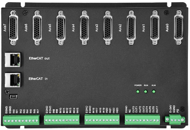
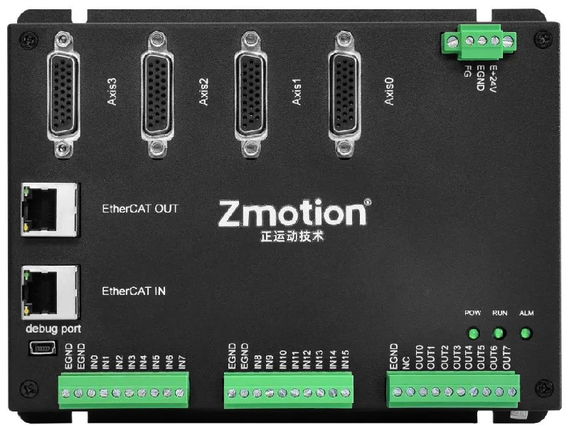
For “How to Use” , you can refer to the former one.
Step 1: Do Hardware Wiring
Step 2: Initialize EtherCAT
Do EtherCAT initialization to build communication connection, in the initialization, you need to map expanded axis and IO to avoid conflict with controller’s resources.
Step 3: Read & Write IO by Command, Control Motor.
Today, let’s see how to test expanded resources by EIO24088-V2 / other EIO modules in our free IDE development software RTSys , that is, after expanded, how to check whether they are valid or not.
Tip: usage and showing are based on RTSys, you can download to simulate by yourself, here is the downloading address. Before using, please refer to RTSys Usage Manual. And even if here shows Chinese RTSys, you can switch it to English by yourself, because they are with same operations. Even you can create and add other needed languages.
1. “How to Test IO Resource”?
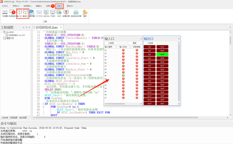
When there is no IO device, in RTSys, we can know IO situation through connecting OUT with IN directly, like below image:
it tests EIO module’s IO configuration, specifically, it connects EIO OUT2 (mapped No. is 34) to EIO24088-V2 IN 8 (mapped No. is 40), then operate OP (34), it can be seen IN 40 gets the signal.
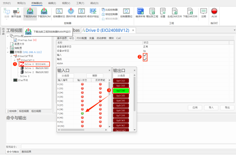
What’s more, you can check “Enable EtherCAT Config” in project setting to test IO resourced expanded by EtherCAT modules.
Step 1: open EIO24088-V2 interface.
Step 2: open EIO24088-V2 IN & OP.
Step 3: connect OUT 2 & IN 7 of EtherCAT module EIO24088-V2, after ON OUT2, IN7 will be 1, which means IO are normal.
2. “How to Test Pulse Axis”?
At first, map the pulse axis that needs to be tested (in ECAT INIT, mapped already, no need map again), for example, test EIO24088-V2 Axis 1.
AXIS_ADDRESS(7)=(0<<16)+1+1 'the second drive on EtherCAT, drive No. is 1, bind it with axis 7
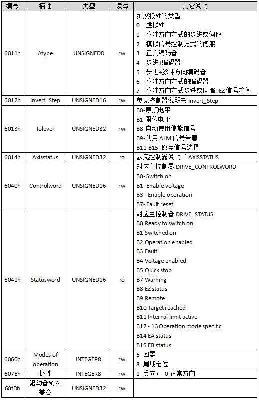
Configure expansion module’s DRIVE_PROFILE as 0, and set ATYPE as 65. However, the expansion is pulse type converted from bus, axis type is not 65, for the real-axis type, please use SDO command to configure data dictionary 6011h.
Ø How to Use SDO Command to Set Drive Parameters?
For example, if it is expanded pulse axis, whose real axis type is set by data dictionary 6011h, you can refer to below form parameters, and set in sequence according to axis No., that is, the first drive sets data dictionary 6011h+0*800h, the second drive sets 6011h+1*800h, and so on, each drive plus 800h. For other parameters, the same rule.
--IN & OP--

--First One Drive on First Expansion Module--
A. How to Read by SDO?
SDO_READ (slot, node, data dictionary No, data dictionary sub No., data type, TABLE position where saves the data)
SDO_READ_AXIS (axis No., data dictionary No., data dictionary sub No., data type, TABLE position where saves the data)
B. How to Write by SDO?
SDO_WRITE (slot, node, data dictionary No, data dictionary sub No., data type, write value)
SDO_READ_AXIS (axis No., data dictionary No., data dictionary sub No., data type, write value)
C. Notes:
Slot: the No. on the bus interface (EtherCAT)
Node: the device No. connected on the controller
D. Example
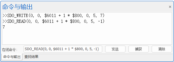
Read node 0 (the first one drive on the controller) EIO24088-V2’s axis 1 axis type.
SDO_WRITE(0, 0, $6011 + 1 * $800, 0, 5, 7) 'set EIO24088-V2 axis 1 type as 7
SDO_READ(0, 0, $6011 + 1 * $800, 0, 5, -1) 'print out axis 1 type
After confirmed ATYPE (axis type), pulse mode, when testing, please set parameters be small at first, like, UNITS (pulse amount), SPEED (running speed), ACCEL (acceleration), DECEL (deceleration). For auto-enable (by 6013H BIT8), check whether axis enable (AXIS_ENABLE) is set as 1. For manual-enable, it needs to set AXIS_ENABLE and corresponding axis’ enable OUT as 1.
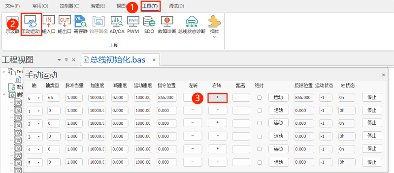
In addition, sending motion command can check motor motion situation, specifically, view DPOS and MPOS parameters. After that, you can fill in UNITS (needed pulses) for drive 1mm movement or in one circle, the now MOVE(1) means 1mm movement or 1 circle turning, please note the SPEED unit is mm/s or r/s.
Notes:
If in manual motion, the axis doesn’t move, but DPOS (demand position) & MPOS (encoder measurement position) change, which means the axis actually moves but not obviously, you can increase UNITS, the move it again.
If in manual motion, the axis only moves to one direction, please check drive axis type, pulse mode (by drive manual or drive software), and see whether axis type set in 6011H matches with pulse mode in 6012H or not, also check the wiring.
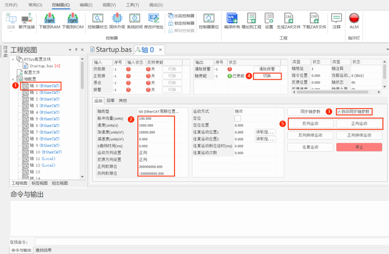
As mentioned above, you also can check through “enable EtherCAT Config” function in RTSys, let’s see specific steps.
Step 1: select which axis to test.
Step 2: set suitable axis.
Step 3: automatically synchronize axis parameters.
Step 4: open axis enable.
Step 5: make axis move forward or reversely to see whether it is normal.
ABOUT ZMOTION
That's all, thank you for your reading -- Expand More Axis & IO by EtherCAT | EIO24088-V2 & EIO16084 (2)
For more information, please pay close attention to "Support" and "Download" , and there are other platforms about Zmotion - Youtube & LinkedIn & Twitter & Tiktok & Facebook, including technical information (development environment, routine code), product showing, company development, etc.
Hope to meet you, talk with you and be friends with you. Welcome!
This article is edited by ZMOTION, here, share with you, let's learn together.
Note: Copyright belongs to Zmotion Technology, if there is reproduction, please indicate article source. Thank you.
Zmotion Technology provides motion control card, motion controller, vision motion controller, expansion module and HMI. ( more keywords for Zmotion: EtherCAT motion control card, EtherCAT motion controller, motion control system, vision controller, motion control PLC, robot controller, vision positioning...)