


In your motion control application, if you need more resources, such as, axis module, IO module, corresponding expansion module can help you. We Zmotion support EtherCAT module and CAN module to extend pulse axis, digital input & output, and analog input & output.
Today, we mainly share two EtherCAT axis and IO modules with you: EIO24088-V2 and EIO16084.
* EIO24088-V2: expand 8 axes + 24 inputs + 8 outputs through EtherCAT.
* EIO16084: expand 4 axes + 16 inputs + 8 outputs through EtherCAT.
Because it follows standard EtherCAT protocol, all kinds of EtherCAT master motion controllers can be matched together. Then, here, we take the example using Zmotion EtherCAT motion controller with EtherCAT module, and it is easy to use. You only need to follow below 3 steps:
Step 1: Do Hardware Wiring
Step 2: Initialize EtherCAT
Do EtherCAT initialization to build communication connection, in the initialization, you need to map expanded axis and IO to avoid conflict with controller’s resources.
Step 3: Read & Write IO by Command, Control Motor.
And above configuration steps, generally they are done in our Zmotion Free IDE Development Software RTSys. You can download it directly.
Therefore, our description will use RTSys to configure these two EtherCAT axis IO modules.
Let’s see details.
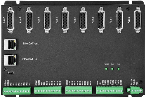
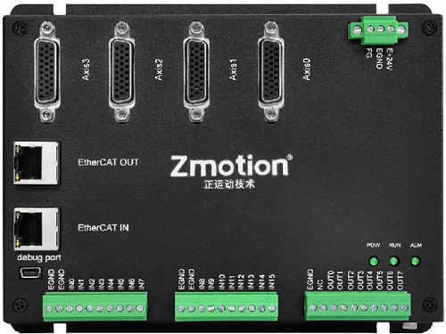
Step 1: How to Wire Your Motion Controller & EIO Modules?
(1) Know Hardware Interfaces (EIO24088-V2)
A. EtherCAT
EIO24088-V2 has two EtherCAT interfaces, EtherCAT IN and EtherCAT OUT. EtherCAT IN connects to main controller or former module, EtherCAT OUT connects to next expansion board. Please note they can’t be used incorrectly!

B. General IN
EIO24088-V2 can expand 24 general digital inputs.
Use NODE_IO command to configure IO address No. at first, then you can operate it.
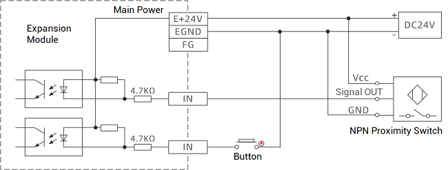
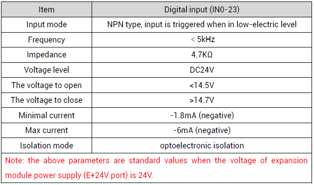
Inner circuit of general IN and IN parameter form as shown below (parameters are based on standard 24V):
--General IN Inner Circuit Reference--
--IN Parameters--
C. General OUT
EIO24088-V2 can expand 8 general digital outputs.
Same as IN, use NODE_IO command to set IO address at first. Actually, NODE_IO command can configure IN and OUT at one time.
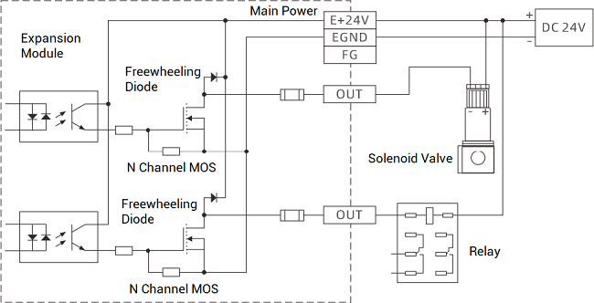
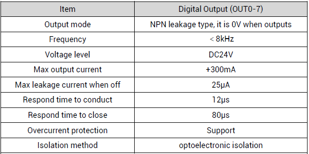
Inner circuit of general OUT and OUT parameter form as shown below (parameters are based on standard 24V):
--General OUT Inner Circuit Reference--
--OUT Parameters--
D. AXIS
EIO24088-V2 can expand 8 pulse axes.
It uses DB26 Pin. And include differential pulse input signal and differential encoder output signal. At the same time, there are one general IN and one general OUT (EIO16084 has 2 general inputs and 2 general outputs).
--PIN Definition--
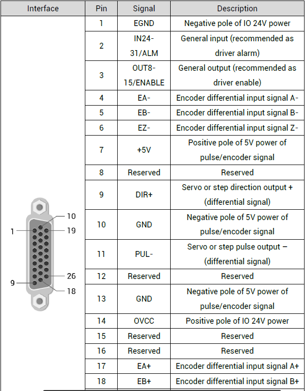
Note: you can configure EIO module by data dictionary 6013h to enable and alarm directly. it doesn’t use by default, it needs main controller to operate.
(2) EtherCAT Wiring Reference (EIO24088-V2)
“EIO24088-V2 can connect to any nodes on the EtherCAT”.
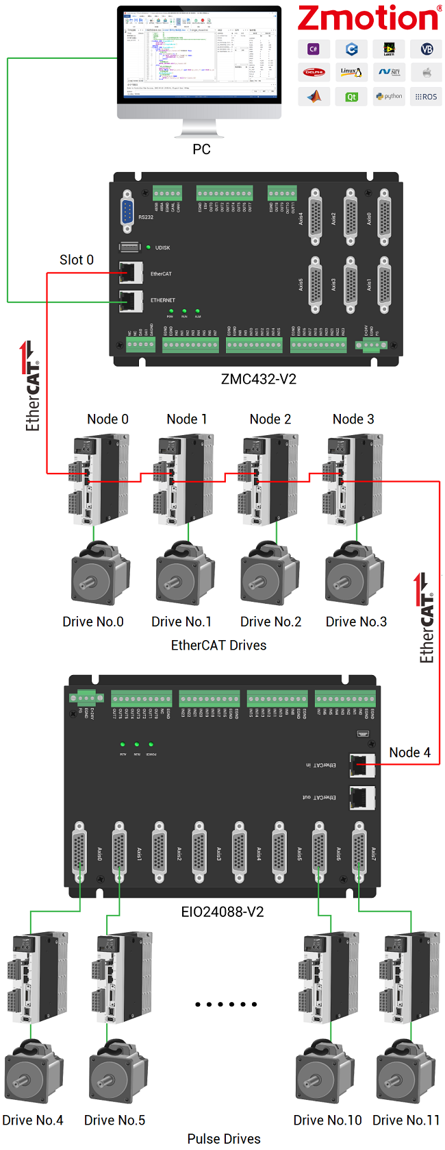
EIO24088-V2 is one device node on the EtherCAT, which can connect to 8 pulse drives. Then the drive will be numbered according to the sequence from AXIS 0 to AXIS 7, and it obeys EtherCAT number rule, also needs to do axis mapping.
Drive enable signal is the general output in pulse axis, the OUT can be triggered by main controller OP command, or using SDO command to configure data dictionary 6013h – BIT8 as 1, then it can enable automatically. And main controller can’t control corresponding OUT to enable, it only needs to set WDOG as 1, and set related axis’ AXIS_ENBALE as 1.
Note: there is limit for the number of axis expansion modules you can use, please refer to your controller’s max axes.
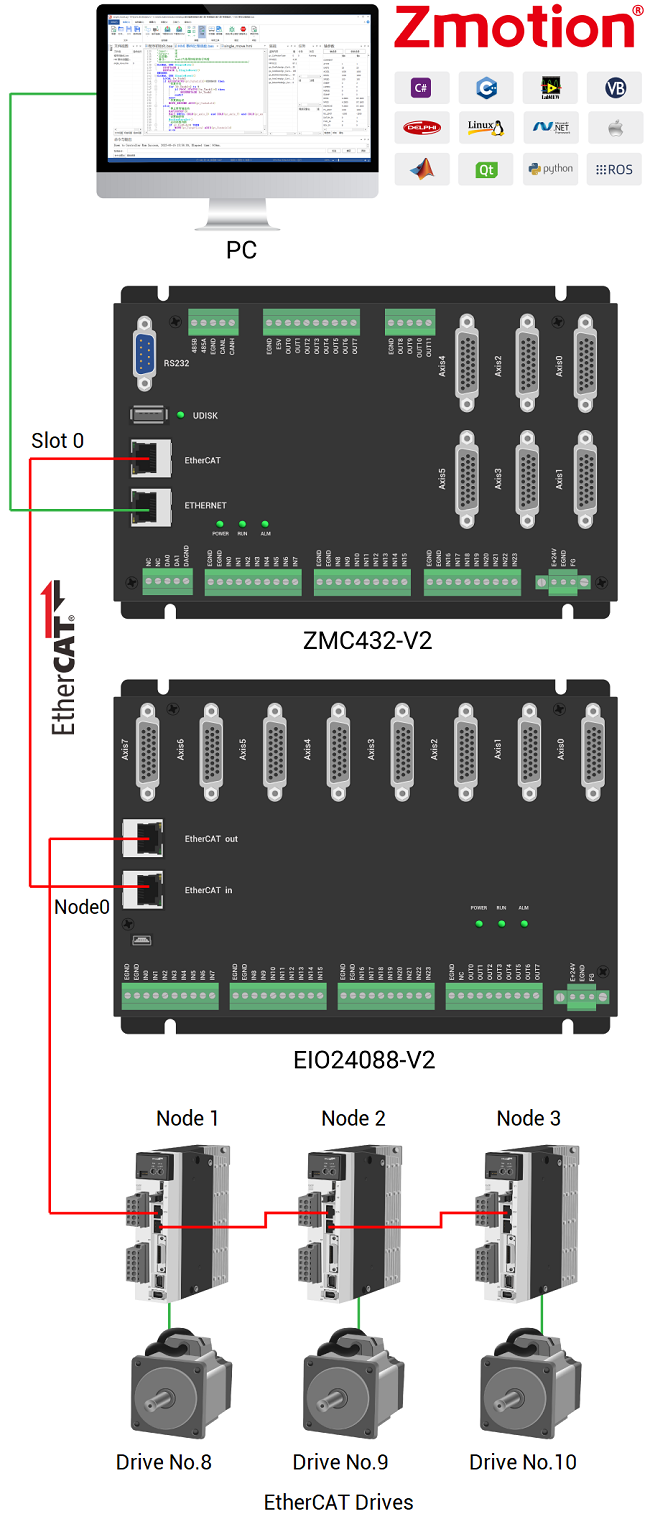
Then, let’s see one wiring example with one EtherCAT motion controller. Here, use ZMC432-V2 EtherCAT motion controller. The controller has 6 local pulse axes. Node 4 connects the EIO module to expand 8 axes. Then, expansion axes are AXIS0-7 (correspond to drive No. 4-11 as below), and they are mapped into axis 10-17 manually. Therefore, please see below graphic, which shows EtherCAT motion controller, EIO expansion module and drives wiring.
--slot--
It indicates the controller bus interface No., default is 0. When there are several bus interfaces, you can confirm by sending online command “?*SLOT" command.
Generally, for single-bus, EtherCAT is 0, for dual-bus, EtherCAT is still 0, RTEX is 1.
--node--
It is device No., which indicates the device No. connected to the “slot”, starting from 0. And it is numbered automatically according to bus connection sequence. You can check how many devices connected totally by NODE_COUNT(slot) command.
--device No.--
It is drive No. connected on the slot, which is mainly for drive. Starting from 0, and controller will automatically detect it. Also, it is numbered automatically according to drive connection sequence on the “slot”.
(3) How to Map Expanded Axis & IO?
Obviously EIO24088-V2 and EIO16084 expansion modules need to map axis and IO, because they can expand these two resourced.
A. Map IO
--How to Map IO--
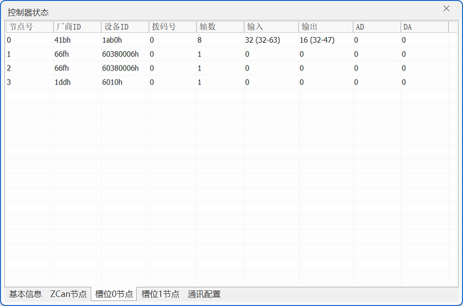
Set IO No. through NODE_IO at first (IN & OUT can be configured synchronously), then, module information can be known by the IO No. And you can check in RTSys – Controller State – Slot0Node.
The specific command: NODE_IO (slot, node)=iobase
For example:
NODE_IO (0, 0)=32 ‘set IO starting No. of the first device connected to EtherCAT as 32
--Notes--
a. before mapping, please check how many IO your controller can support (external IO + IO in pulse axis), the use command to set.
b. controller IO No. and expanded IO No. can’t be the same.
c. “slot” and “node” refer to above description, “iobase” means IO starting No., which only can be multiple of 8.
d. in the example, if the first device is EIO24088-V2, after configured by the command, the starting No. has already mapped as 32, then IN No. range will be 32-63 because it has 32 inputs itself (24 general inputs + 8 inputs in AXIS & can’t be the same), OUT No. range will be 32-47 (8 general outputs + 8 inputs in AXIS & can’t be the same & same configured with IN).
B. Map Axis
Use AXIS_ADDRESS command to map extended axis No.
Don’t make No. be same!
The specific command: AXIS_ADDRESS (axis No.) = (Slot << 16) + Drive No. + 1
For example:
AXIS_ADDRESS(0)=(0<<16)+0+1 'first drive on EtherCAT, drive No. is 0, bind with axis 0
AXIS_ADDRESS(1)=(0<<16)+1+1 'second drive on EtherCAT, drive No. is 1, bind with axis 1
If the first node is EIO24088-V2, drive No.0 connects to the first drive (convert bus to pulse) on the EIO24088-V2.
Step 2: How to Initialize EtherCAT?
For EtherCAT bus module, it needs initializing at first, below shows the whole initialization process.
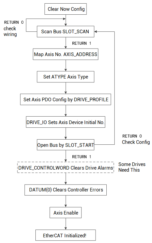
Actually there are 2 methods to achieve that:
* method 1: use Zmotion provided EtherCAT initialization basic program in RTSys.
* method 2: use axis configure & EtherCAT configure in RTSys project setting.
Today, let’s see one by one.
--Method 1: Use General Initialization Program--
It can initialize EtherCAT drive and EtherCAT expansion module, build communication connection.
Note: it is general example, multiple brands’ drives are OK.
A. Build one Project in RTSys / ZDevelop
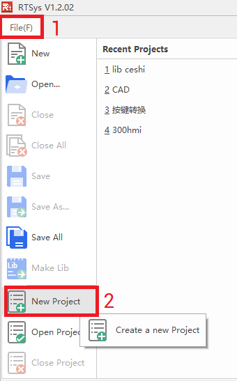
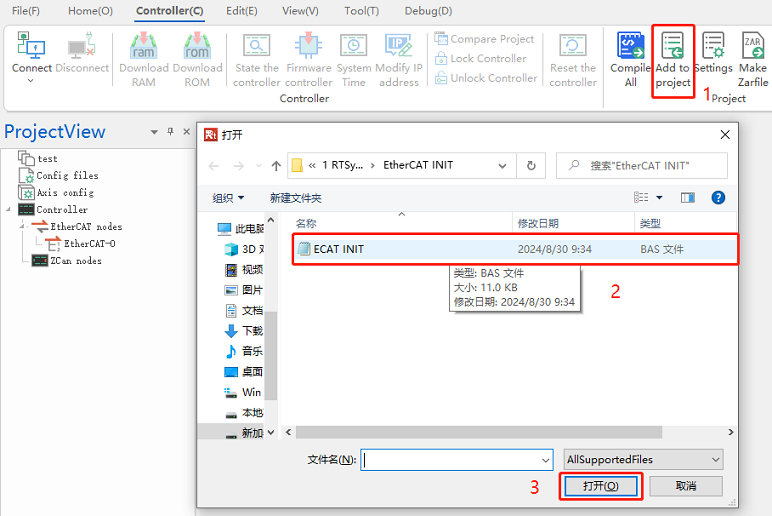
B. Add “ECAT Init” project file into the project.
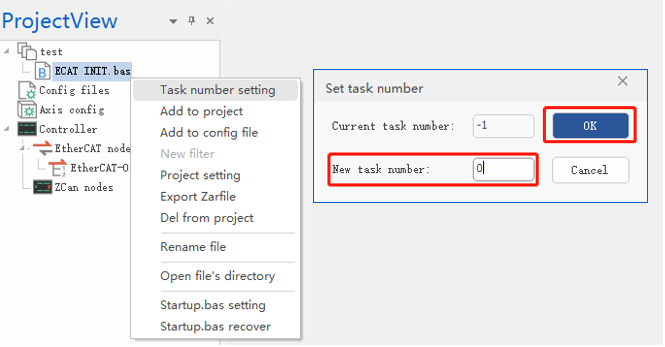
C. Set task No. for the ECAT INIT basic file.
D. Set how many local pulse axes, starting No., and bus axis starting No.
If you don’t use local pulse axis, only use EtherCAT axis, you can use default configuration (if not, you only need to modify corresponding parameter). In the general initialization program, using 6 local pulse axes, connecting one EIO24088-V2, two Panasonic drives, and one DELTA drives on the EtherCAT.
EtherCAT Initialization Program (it only shows former part codes, for full program, you can download from here):
'*******************************************************ECAT Bus Initialization
global CONST BUS_TYPE = 0 'bus type. (can be used to distinguish the current bus type for host computer)
global CONST MAX_AXISNUM = 16 'max axes
global CONST Bus_Slot = 0 'slot No.: 0 (for single bus controller, default is 0)
global CONST PUL_AxisStart = 0 'local pulse-axis starting axis No.
global CONST PUL_AxisNum = 0 'the number of local pulse axes
global CONST Bus_AxisStart = 0 'bus axis starting axis No.
global CONST Bus_NodeNum = 1 'configure the number of nodes to see whether it is consistent with real detected number of slave station
global Bus_InitStatus 'bus initialization completion state
Bus_InitStatus = -1
global Bus_TotalAxisnum 'check how many axes in total scanned
delay(3000) 'delay 3s, wait for the drive to be powered on. (Adjust the delay according to the drive).
?"Bus Communication Period:",SERVO_PERIOD,"us"
Ecat_Init() 'initialize ECAT bus
while (Bus_InitStatus = 0)
Ecat_Init()
wend
end
'***************************************************ECAT Bus Initialization****************************************
'how to initialize: slot_scan (scan the bus) -> slave station node map the axis I/O -> SLOT_START (open bus) -> success to initialize
'******************************************************************************************************
global sub Ecat_Init()
local Node_Num,Temp_Axis,Drive_Vender,Drive_Device,Drive_Alias
RAPIDSTOP(2)
for i=0 to MAX_AXISNUM - 1 'restore axis type
AXIS_ENABLE(i) = 0
atype(i)=0
AXIS_ADDRESS(i) =0
DELAY(10) 'prevent all drivers from being switched to enable at the same time, causing excessive instantaneous current.
next
Bus_InitStatus = -1
.......
In a short, the full process is “you connect these EtherCAT devices well, then use above program to initialize EtherCAT and build communication. After that, you can see current connected devices information in “controller state””.
In the ECAT INIT program, main station is the controller, the first slave device is EIO24088-V2 expansion module, remaining 3 slave devices are EtherCAT drives, controller local pulse axis interfaces can be used. And EtherCAT drive device mapped axis No. starts from 0, that is, pulse drives of EIO24088-V2 AXIS 0-7 are mapped as axis 0 – axis 7, 3 EtherCAT drives are mapped as axis 8 – axis 10, local axis starts from 11, IO starting No. of EIO24088-V2 is 32.
--Method 2: Configure EtherCAT Initialization in RTSys Project Setting by Yourself--
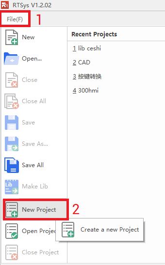
A. Build one new project in RTSys.
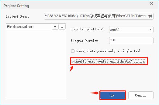
B. Open EtherCAT configure.
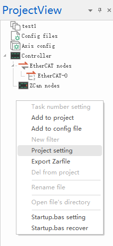
In ProjectView, right click it, and select “project setting”, then check “Enable axis config and EtherCAT config”.
C. Scan which EtherCAT node to be configured

D. Configure axis No. & type by yourself
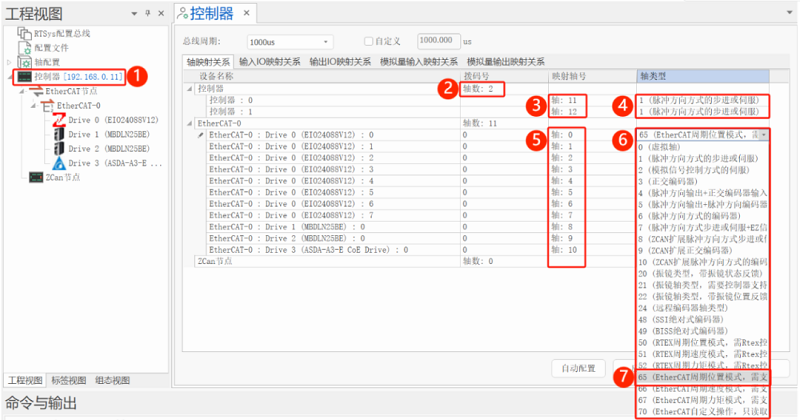
a. double click “controller” to open controller configuration interface.
b. select how many local pulse axes you need (here select 2 pulse axes).
c. remap local pulse axis No.
d. select axis type (ATYPE) for local pulse axes according to real needed.
e. map axis No. for scanned EtherCAT axis
f. set axis type
g. select 65/66/67 according to real situation (different axis types need different PDO lists)
h. click “apply” to generate Startup.bas file automatically.
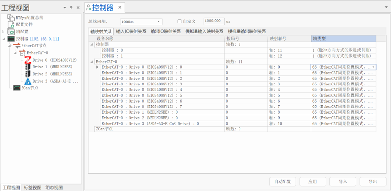
It can be seen it configured 2 local pulse axes (axis No. are remapped as 11 and 12), 8 axes (from EtherCAT to pulse) of EIO24088-V2 (axis No. are mapped as 0-7),2 Panasonic bus servo drives, and one ServoTronix bus servo drive (axis No. are mapped a 8-10).
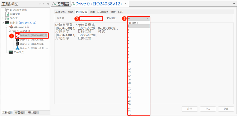
E. Set PDO as needed.
a. select needed node (here select EIO24088-V2).
b. select needed axis (here select 8 axes).
c. set PDO (select 0).
d. after all axes configured, click “apply” to save the configuration.
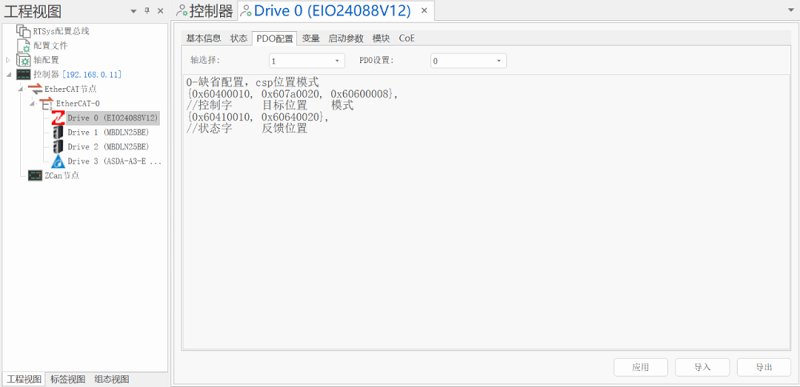
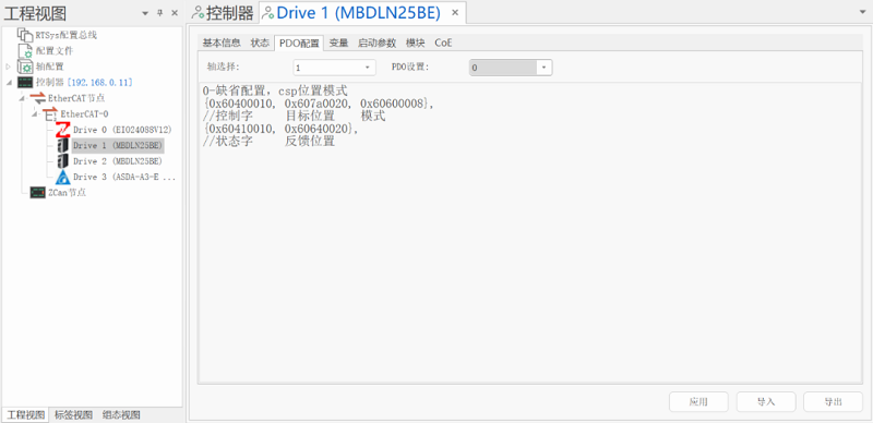
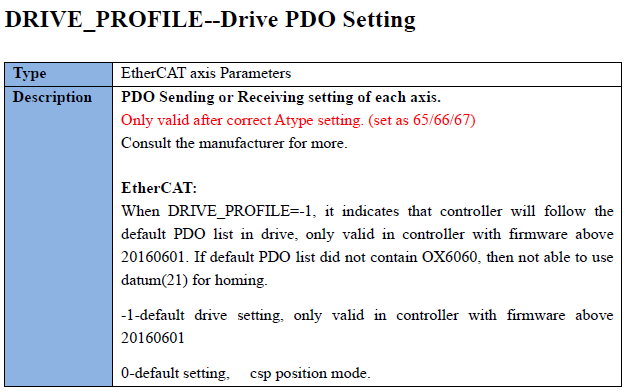
(for command details, please refer to Basic Programming Manual)
F. Download the Startup.bas into controller
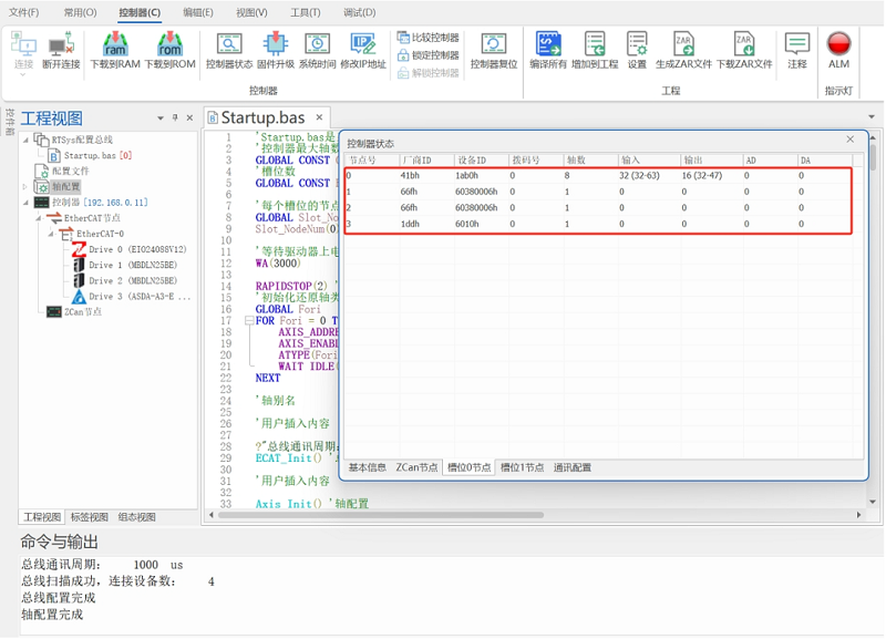
Step 3: Read & Write IO by Command, Control Motor
After step 1 and step 2, you can do data interaction, needed resources can be achieved.
Actually before that, you can test whether you complete step 1 and step 2 or not. “How to Test Expanded Resources” will be shown in next article.