


From the article name, it can be known the theme is
how to use EtherCAT motion controller for SCARA manipulator. Of course, EtherCAT is not only for SCARA manipulator, Zmotion ethercat motion controller can be used more than 30 kinds of robotic arms, like, standard SCARA, delta, palletizing, 6-joint, etc., and before, we have already talked about “EtherCAT Motion Controller on Delta” , you can review them (3 parts in total) in details. And in next article, EtherCAT Motion Controller on Palletizing.
Here, we mainly show you:
--one cost-effective & multi-axis EtherCAT motion controller XPLC104H8R--
--standard SCARA manipulator model--
--one routine example--
Hardware Introduction: EtherCAT Motion Controller & HMI
ZMOTION TECHNOLOGY
A. EtherCAT Motion Controller: XPLC104H8R
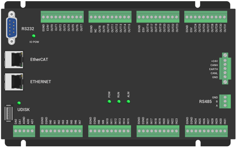
XPLC104H8R is one cost-effective & multi-axis EtherCAT + pulse motion controller, which has many communication interfaces, EtherCAT, EtherNET, RS232, CAN, U disk, etc.
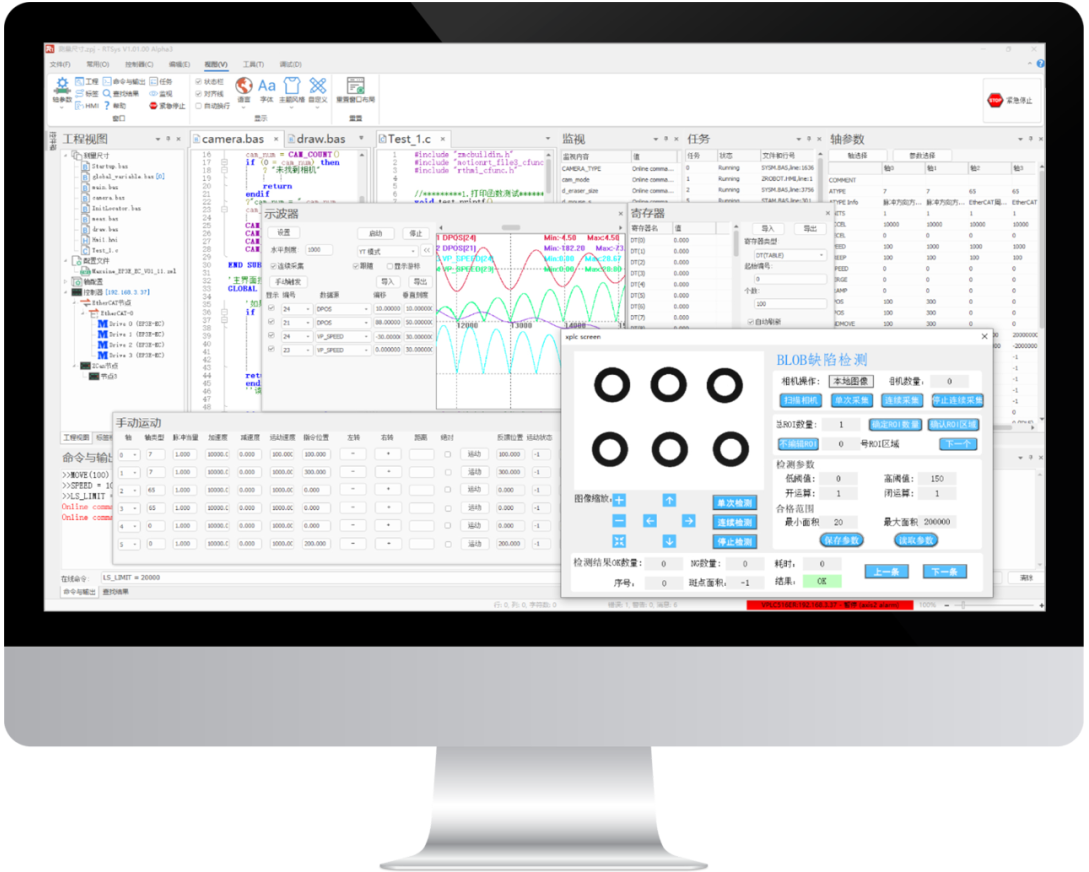
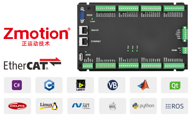
For Zmotion motion control products, secondary development is needed. There are 2 methods, if you master PC programming languages (C#, C++, LabView, python, etc.), you can directly call our uniform encapsulated PC function library commands to control corresponding motions. If not, Zmotion provides 3 programmable methods in RTSys (Zmotion IDE development & debugging software), Basic, PLC, and HMI, and they can be used together.
XPLC104H8R, this motion controller supports 4 axes, if you need more, it also can be expanded to 32 axes.
a. motion control resources
4-axis motion control, 32 INs & 32 OUTs, 2 ADs & 2 DAs, EtherCAT refresh period is 1ms.
b. motion control functions
linear interpolation, any circular interpolation, helical interpolation, electronic cam, electronic gear, synchronous follow, etc.
c. motion control applications
this controller belongs to economical type, but also can be used in electronic semi-conductor devices (detection equipment, assembly line equipment, locking equipment, soldering equipment), dispensing devices, non-standard devices, printing & package devices, textile & garment devices, medical equipment, etc.
PS: Motion Controller VS PCI Motion Control Card
--no need slot, more stable--
--can use MINI PC / ARM IPC, lower cost--
--be used as wiring board, less space--
--run program directly, only interact with PC, lower requirements on PC software--
B. HMI: ZHD400X
XPLC controllers support SCARA. It downloads edited program into controller (also can watch information by PC / send command in real time), then use HMI teaching to edit needed motion trajectory.
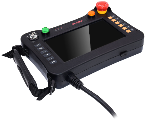
ZHD400X is one touch screen teach pendant that shows information by network. Teach pendant must be used together with the controller that supports ZHMI function, and you’d better to use latest version’s development software ZDevelop (RTSys).
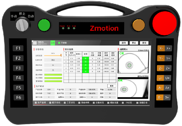
Above shows ZHD400X, it has 18 keys, and emergency stop switch is built. The resolution is 800*480, showing in real colors.
Standard SCARA Manipulator Model
ZMOTION TECHNOLOGY
FRAM1 -- Standard SCARA
SCARA Manipulator (Robotic Arm) supports 2-4 axes , that is, big joint axis + small joint axis [+ axis Z] [+ end rotary axis].
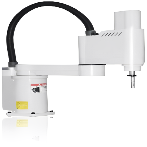
Here, this system uses standard 4-axis SCARA manipulator, 2 joint axes X and Y, one up and down axis Z, and one terminal turntable axis R.
How to Use SCARA Robotic Arm
Step 1: Check Motor Turntable Direction
Motor direction, angle range definition, and each joint motor forward should be consistent with "blue arrow" of below image.
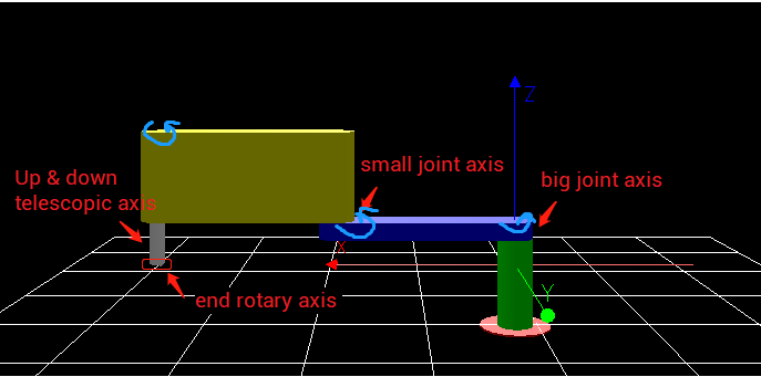
*big joint-axis: the angle / movement angle is (-2π, 2π).
*small joint-axis: the angle / movement angle is (-2π, 2π).
*end turntable axis: no limit of angle / movement angle.
*telescopic shaft up and down: limited by mechanical structure.
Step 2: Determine the Axis Sequence (Manipulator Each Joint-Axis -- Controller Command Parameter)
Select each joint-axis axis No. and corresponding virtual-axis axis No.
--real robot joint-axis & define abbreviation--
big joint-axis motor = Axis_a
small joint-axis motor = Axis_b
end turntable axis = Axis_c
telescopic shaft up and down = Axis_d
--Cartesian coordinate system virtual axis & define abbreviation--
translation axis X = Viraxis_x
translation axis Y = Viraxis_y
turntable axis RZ = Viraxis_v
translation axis Z = Viraxis_z
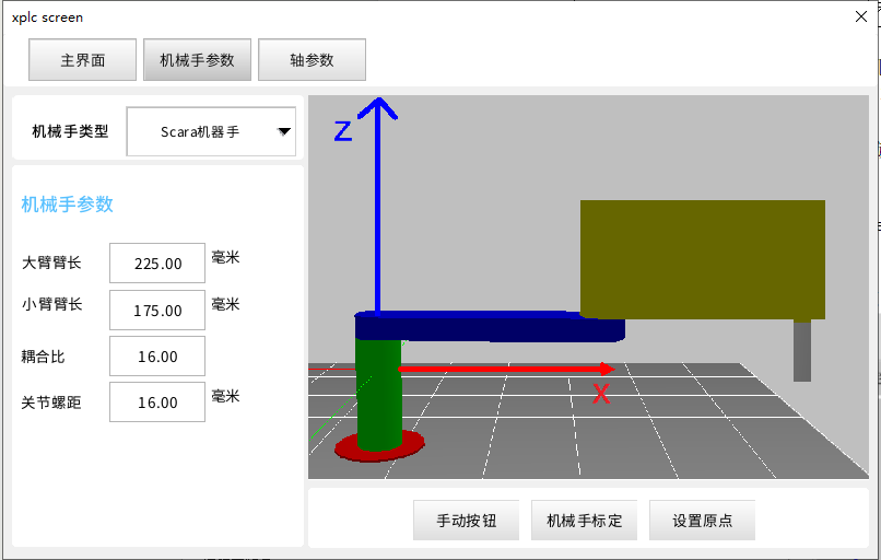
Step 3: Set Mechanical Parameters in TABLE
While building the manipulator connection, it needs to fill in below mechanical parameters into TABLE array as order.
TABLE(tablenum, L1,L2, Pules1OneCircle, Pules2OneCircle,[Pules3OneCircle,L3] [,ZDis])
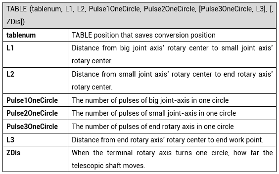
In below routine, fill in Frame required mechanical parameters starting from TABLE(10000).
Step 4: Set Motor Parameters
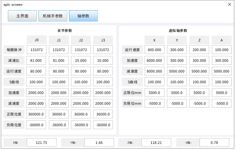
Please set correct axis types and UNITS (pulse amount) of each axis. For UNITS of virtual-axis, actually its is irrelevant with real sent pulses, which is used to set motion precision, generally, UNITS (pulses) in one mm is set as 1000, that is, the precision can reach 0.001. In addition, all manipulator axes should use same length unit, usually it is mm.
In this routine, it is set well, no need to set again.
Step 5: Move Each-Axis to Planned Origin Position
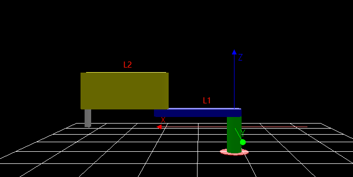
When building manipulator algorithm, it needs one origin position as reference, at the same time, it needs to determine the motor direction.
For SCARA, its origin position is confirmed when the two joint axes' origins become one straight line, at this time, it points virtual-axis X +.
Coordinate Direction: when the joint axis is the origin, virtual-axis' origin coordinate is (L1+L2, 0). For up & down axis, no special requirements on the its origin position. And after building reverse connection, virtual axis' DPOS (demand position) will correct as (L1+L2, 0) automatically.
Step 6: Build Robotic Arm Forward / Reverse Kinematics
A. Build Forward Kinematic
Select corresponding manipulator model at first, because different models correspond to own TABLE list. Then use command "CONNREFRAME" to build forward mode. Next, select the model's axis list. For command information, please refer to "ZBasic Programming Manual".
TABLE(ScaraTableId,ga_L1,ga_L2,JOnePulses(0),JOnePulses(1),JOnePulses(2),ga_L3,ga_Ratio) 'SCARA manipulator parameters list
TABLE(MaDuoTableId,LargeX,LargeZ,JOnePulses(0),FRAME3_L1,FRAME3_L2,JOnePulses(1),JOnePulses(2),SmallX,SmallZ,JOnePulses(3))'standard palletizing manipulator parameters list
RAPIDSTOP(2)
IF Mode=1 THEN
'robotic arm forward solution
IF Roobat_Flag= 0 THEN 'Scara robotic arm forward is built
BASE(gcAxisVx,gcAxisVy,gcAxisVu,gcAxisVz) 'select axis list
CONNREFRAME(1,ScaraTableId,gcAxisJ1,gcAxisJ2,gcAxisJu,gcAxisJz)
WAIT LOADED 'wait for the motion to be loaded
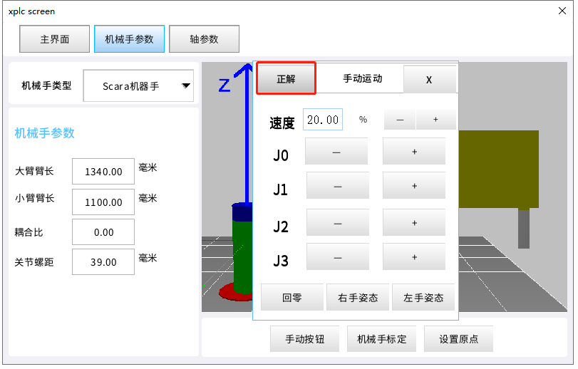
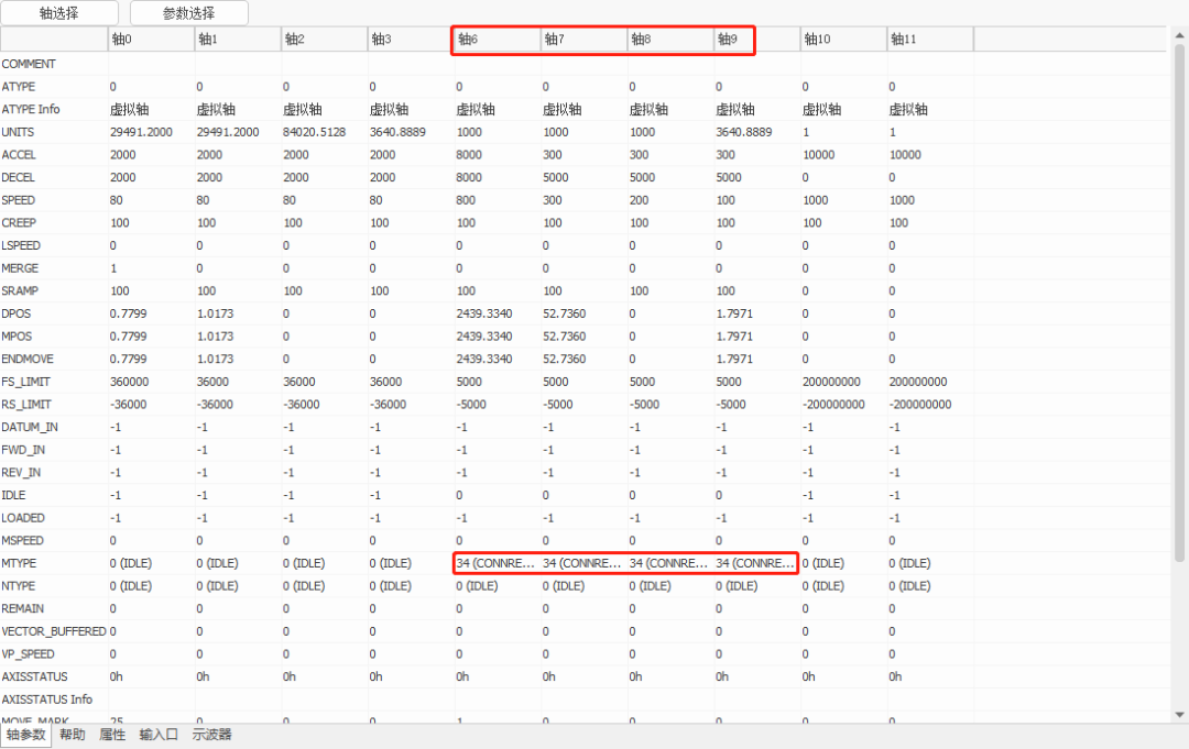
After building successfully, virtual-axis' MTYPE (current motion type) will be shown as 34, and at this time, only joint-axis can be operated in joint coordinate to adjust manipulator attitude. In addition, in "Manual" ("Tool" -- "Manual") interface in RTSys, we can select joint-axis No. (here, this article uses axis 0 (J0), axis 1(J1), axis 2(J2), axis 3(J3)), then, according to real needs, select "inch motion" / "point motion". And virtual-axis will automatically calculate the position of end work point in the Cartesian coordinate system.
B. Build Reverse Kinematic
Select corresponding manipulator model at first, because different models correspond to own TABLE list. Then use command "CONNFRAME" to build reverse mode. Next, select the model's axis list. For command information, please refer to "ZBasic Programming Manual".
IF Roobat_Flag= 0 THEN 'build Scara robotic arm reverse
BASE(gcAxisJ1,gcAxisJ2,gcAxisJu,gcAxisJz) CONNFRAME(1,ScaraTableId,gcAxisVx,gcAxisVy,gcAxisVu,gcAxisVz) 'axis 6 / 7 as virtual axis X,Y, open the reverse kinematics
WAIT LOADED 'wait for the motion to be loaded, at this time, it will automatically virtual-axis position
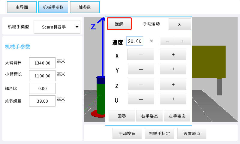
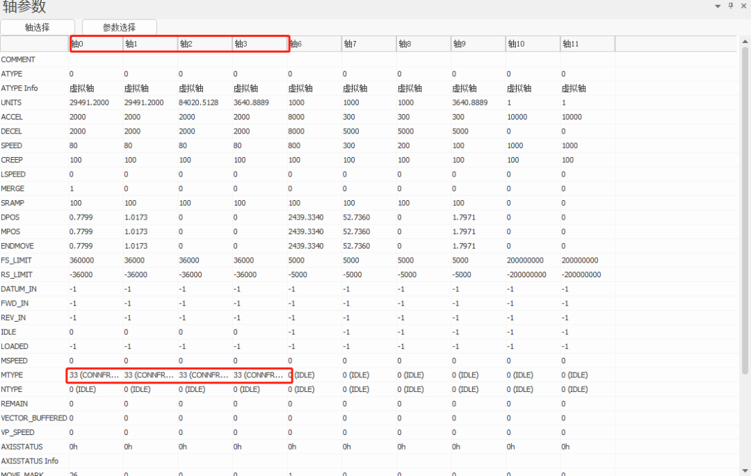
After building successfully, joint-axis' MTYPE (current motion type) will be shown as 33, "manual" operation method is same as above. At this time, for processing technology commands, only virtual-axis can be operated, then edited motion trajectory will move in Cartesian coordinate system (here, this article uses virtual axes, axis 6, axis 7, axis 8, axis 9), also, joint-axis will automatically calculate how to do joint motion in the joint coordinate system.
EtherCAT Motion Controller on SCARA Manipulator Example
ACADEMIC
PRESENTATIONS
Next, let's show one example for you.
As usual, use our own IDE debugging and development software, RTSys (ZDevelop). It supports Basic, HMI, and PLC hybrid programming. In this routine, combine Basic with HMI interface.
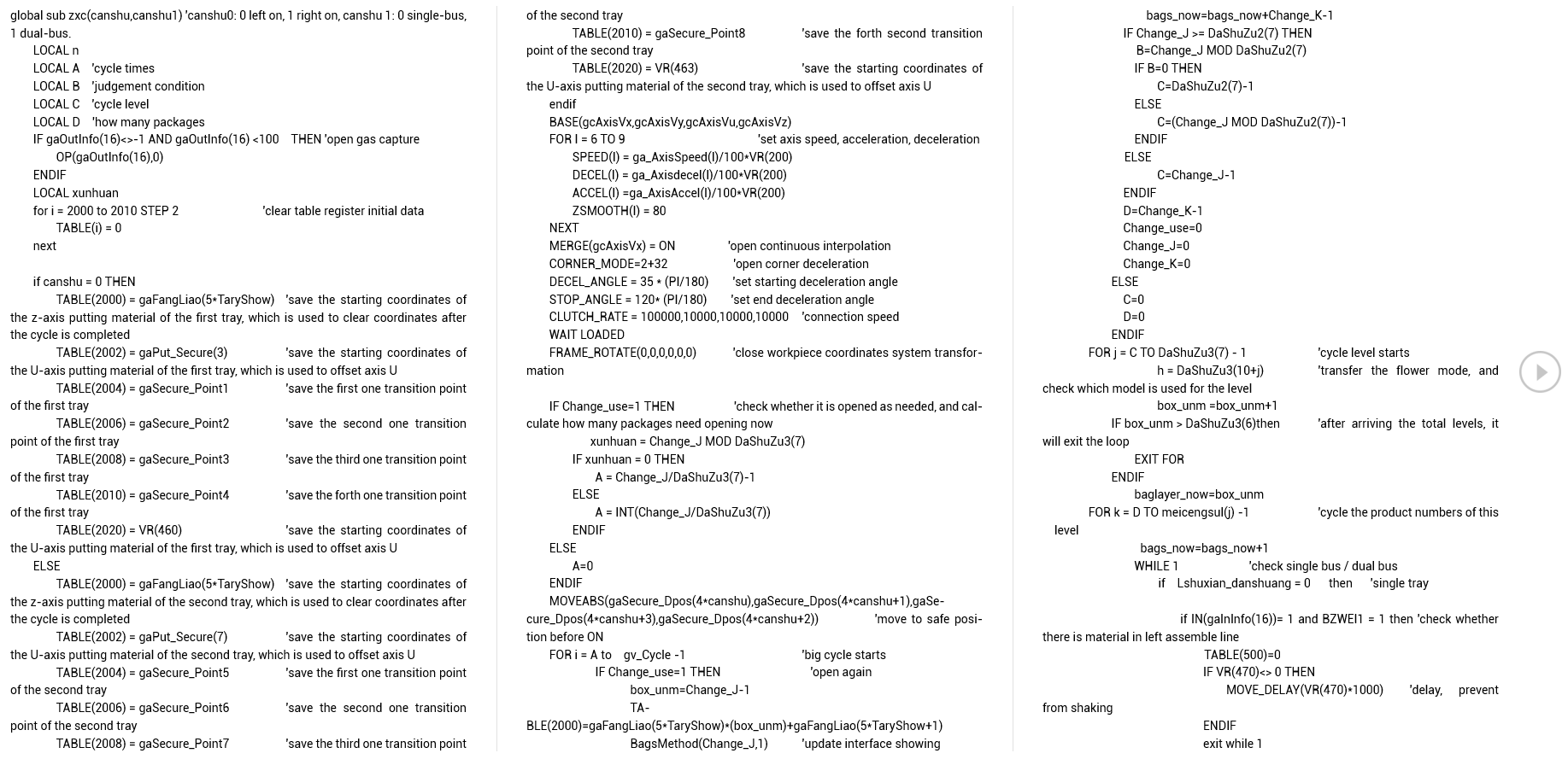
Below shows the routine Basic codes:
global sub zxc(canshu,canshu1) 'canshu0: 0 left on, 1 right on, canshu 1: 0 single-bus, 1 dual-bus.
LOCAL n
LOCAL A 'cycle times
LOCAL B 'judgement condition
LOCAL C 'cycle level
LOCAL D 'how many packages
IF gaOutInfo(16)<>-1 AND gaOutInfo(16)<100 THEN 'open gas capture
OP(gaOutInfo(16),0)
ENDIF
LOCAL xunhuan
for i = 2000 to 2010 STEP 2 'clear table register initial data
TABLE(i) = 0
next
following, please contact us.
Then, download it into controller for running. And click RTSys "Tool" -- "Plug-in" -- "XPLC SCREEN".

When HMI interface appears, click "menu" button, select structure parameter, and enter the password, or directly press "F3" button on the ZHD400X, also enter the password. Next, select corresponding robotic arm model and configure corresponding structural parameters.
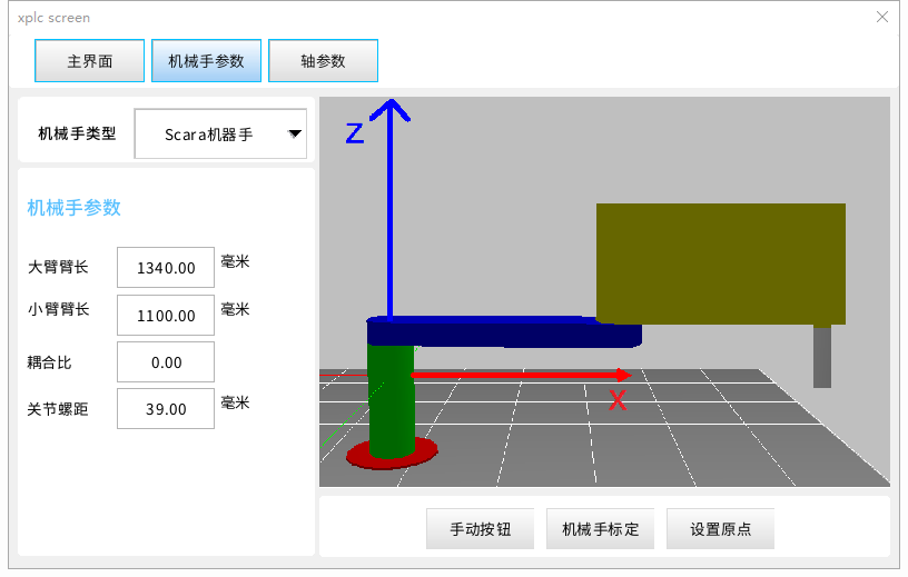
After that, click "axis parameter" to do axis parameters configuration.
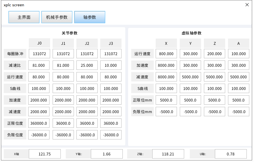
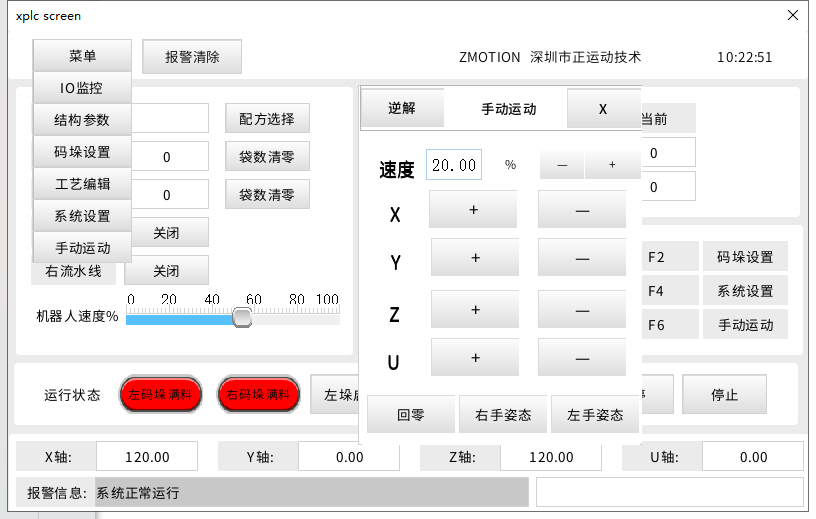
Return to main interface through "main" button, and click "menu" -- "manual", or click "F6" button in the ZHD400X to call manual interface. Then, switch forward and reverse kinematics, and operate corresponding axis to do motion.
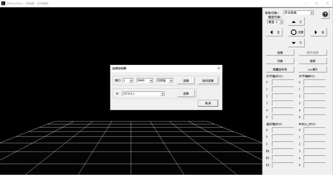
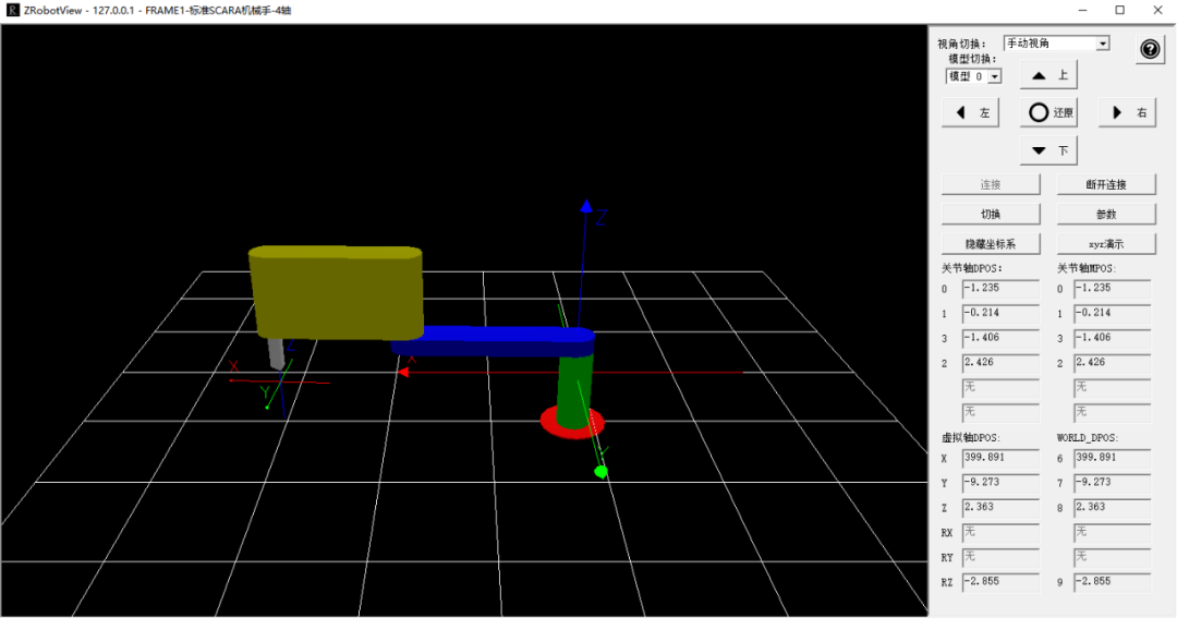
At the same time, you can use our Zmotion robotic arm simulation tool. Open ZRobotView software, and click connect through controller IP (default its 192.168.0.11). After connected, click switch, then you can enter 3D simulation.
ABOUT ZMOTION
That's all, thank you for your reading -- EtherCAT Motion Controller on SCARA Manipulator
For more information, please pay close attention to "Support" and "Download" , and there are other platforms about Zmotion - Youtube & LinkedIn & Twitter & Tiktok & Facebook, including technical information (development environment, routine code), product showing, company development, etc.
Hope to meet you, talk with you and be friends with you. Welcome!
This article is edited by ZMOTION, here, share with you, let's learn together.
Note: Copyright belongs to Zmotion Technology, if there is reproduction, please indicate article source. Thank you.