

Review:
Delta Parallel Robotic Arm by C# | How to Do Kinematic and Manual
Now:
Delta Parallel Robotic Arm by C# | How to Do Camera Calibration & Shape Matching
Next:
Delta Parallel Robotic Arm by C# | How to Do Synchronous Sorting
Therefore, today, Zmotion shares "how to calibrate camera and match shape through C# for Delta robotic arm" , that is, the vision part.
Then, we combine our "vision motion controller" with C# to achieve that.
"Vision Motion Controller" -- "VPLCXXX" -- "VPLC711"
VPLC711 is one Windows high-performance machine vision EtherCAT motion controller based on x86 platform. It is not powerful, but also is flexible, like, multi-channel high-speed hardware IN and multi-channel high-speed PSO OUT, these two kinds of functions can achieve multi-axis synchronous motion precisely, and do multi-protocol high-speed communication with external devices.
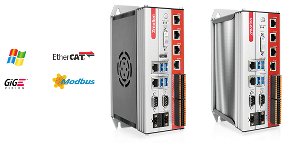
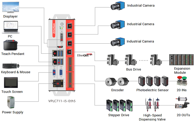
VPLC711 EtherCAT vision motion controller has many kinds of hardware interfaces and communication protocols, which means it is easy to connect and integrate with other devices. And it supports vision processing function, specifically, it can real-time process image data, then achieve vision detection, vision measurement, vision positioning, etc.
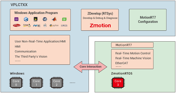
What's more, there is one motion control real-time kernel MotionRT7 built in VPLC711, which can provide one flexible integrated motion control + vision control solution.
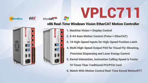
For more information, like, specific resources, hardware wiring, please check corresponding manual -- VPLC711 EtherCAT Vision Motion Controller User Manual.
Here, use VS2010.
Step 1: Build One Project
--click "File" - "New" - "Project"--
--select "Visual C#", .Net Framework 4 and Windows program--
Step 2: Obtain Zmotion C# Library
--method 1: find corresponding library in Zmotion website "download", then download by yourself--
--method 2: contact us, send the corresponding library to you--
Step 3: Develop by Zmotion C# Library File
Note: the downloaded library is "motion control library", if you need vision function, please obtain vision library from us.
--copy "Zmcaux.cs" (motion library) and "Zvision.cs" (vision library) files into new built project--
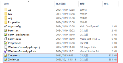
--put zauxdll.dll, zmotion.dll, and zvision.dll files into folder of bin\debug--

--open the file, and click "show all files" in the "solution resource manager", and right click "Zmcaux.cs" and "Zvision.cs" files, then click "include in project".
Step 4: Edit
--double click "Form 1" of "Form 1.cs"--
--edit "using cszmcaux" and "using ZVision" at the beginning--
--state controller handle "g_handle"--
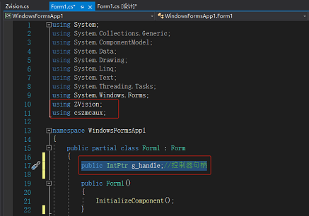
In "PC Function Library Programming Manual”, you can check all encapsulated commands. It can be downloaded here or contact us directly.
Here, it will show Delta related commands.
(1) Connect to Controller -- ZAux_OpenEth
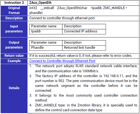
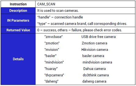
(2) Scan Camera -- CAM_SCAN
(3) Acquit Image -- CAM_GET

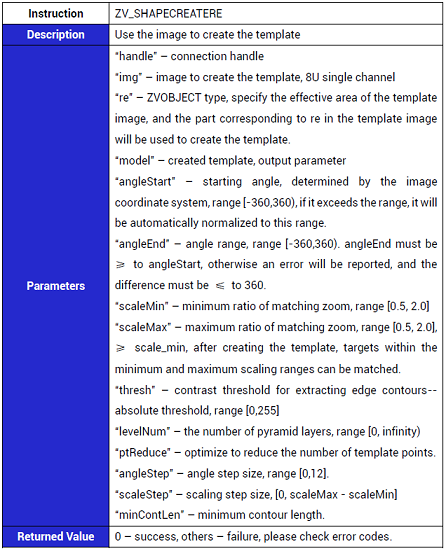
(4) Create Template by Image -- ZV_SHAPECREATERE
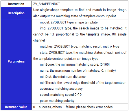
(5) Match Shape & Output Contour State -- ZV_SHAPEFINDST
(1) How to Download Vision Configuration File
At first, it needs to define "vision processing" related variables in the controller before development, because our vision algorithm is executed in the controller.
Generally, vision variables in the Zmotion controllers use ZVOBJECT. For example, we can create one new .bas file, then enter "GLOBAL ZVOBJECT ZVOBJ (1000)" to do vision variable array's definition. After it is saved, download this .bas file into controller when initializing system by PC interface.
//download relative script to controller, then define vision variables
string BasPath = "";
BasPath = string.Format(@"{0}", Application.StartupPath) + @"\Icon\Vision Var Define.bas";
//.bas file is downloaded into controller
zmcaux.ZAux_BasDown(g_Handle,BasPath,0);
(2) How to Calibrate Camera
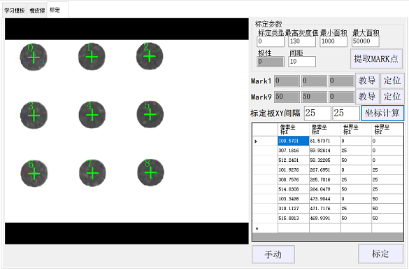
A. Operation Steps
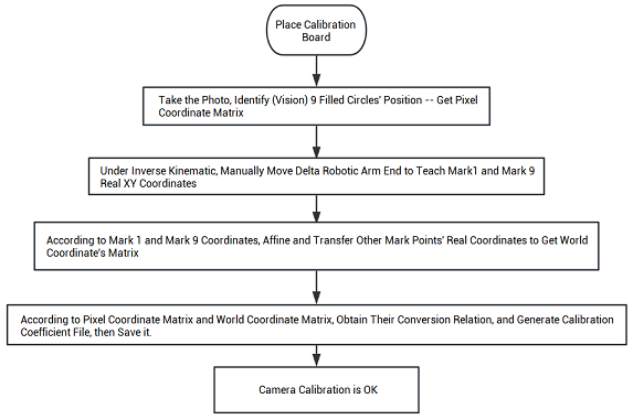
B. Relative Functions' Codes
/************************************************************************************
'Task No.: /
'Function of this function: visually extract the pixel coordinates of the solid circle on the calibration plate and obtain the matrix of the pixel coordinates of the center of the calibration plate.
'Input: /
'Output: /
'Returned Value: /
**************************************************************************************/
private void GetPictureMark()
{
float[] temp_thresh = new float[2];
int Err = 0;
//extract circle center’s image coordinate, obtain pixel coordinate’s matrix “Inppts”
Err = Zvision.ZV_CALGETSCAPTS(form.g_Handle, grabimg, inppts, Convert.ToUInt32(C_CalibThresh.Text), Convert.ToUInt32(C_CalibPolar.Text), Convert.ToUInt32(C_CalibMinArea.Text), Convert.ToUInt32(C_CalibMaxArea.Text));
int[] inppts_info = { 0, 0, 0 };
//obtain matrix’s row and column, row means how many filled circle detected
Err = Zvision.ZV_MATINFO(form.g_Handle, inppts, inppts_info);
int row, col;
row = (int)inppts_info[0];
col = (int)inppts_info[1];
//identify 9 filled circles by vision, it is consistent with circles in the calibration board
if (row == 9)
{
Err = Zvision.ZV_GRAYTORGB(form.g_Handle, grabimg, calibshowimg);
//inppts sort and output, the sorted pixel coordinate matrix ppts
Err = Zvision.ZV_CALGETPTSMAP(form.g_Handle, inppts, ppts, wpts, Convert.ToSingle(C_CalibDis.Text));
Err = Zvision.ZV_MATINFO(form.g_Handle, ppts, inppts_info);
row = (int)inppts_info[0];
col = (int)inppts_info[1];
if (row >= 9)
{
uint i;
DataGridView1.Rows.Clear();
for (i = 0; i < row; i++)
{
//UI interface of pixel coordinates in the WinFrom is displayed
string[] tempstr = new string[4];
float[] outvalue = { 0, 0 };
Zvision.ZV_MATGETROW(form.g_Handle, wpts, i, 2, outvalue);
tempstr[2] = "0";
tempstr[3] = "0";
Zvision.ZV_MATGETROW(form.g_Handle, ppts, i, 2, outvalue);
tempstr[0] = outvalue[0].ToString();
tempstr[1] = outvalue[1].ToString();
DataGridView1.Rows.Add(tempstr);
//in the original image, draw and identify filled circle, and mark, then show the image in the UI interface
Zvision.ZV_MARKER(form.g_Handle, calibshowimg, outvalue[0], outvalue[1], 0, 40, 0, 255, 0);
Zvision.ZV_TEXT(form.g_Handle, calibshowimg, i.ToString(), outvalue[0] - 20, outvalue[1] - 20, 40, 0, 255, 0);
Zvision.ZV_LATCHCLEAR(form.g_Handle, 0);
Zvision.ZV_LATCHSETSIZE(form.g_Handle, 0, Convert.ToUInt32(pictureBox5.Width), Convert.ToUInt32(pictureBox5.Height)); pictureBox5.Image = Zvision.ZV_LATCH(form.g_Handle, calibshowimg, 0);
}
}
else
{
MessageBox.Show("Extract Mark Failed!", "Hint");
}
}
else
{
MessageBox.Show("Extract Mark Failed!", "Hint");
}
}
/************************************************************************************
'Task No.: /
'Function of this function: camera calibration
'Input: /
'Output: /
'Returned Value: /
'Note: calculate conversion relation between pixel coordinates and world coordinates
'Note: obtain the center circle of calibration board’s world coordinate through teaching
**************************************************************************************/
private void CamCalib()
{
//matrix row and column
uint row, col;
row = 9;
col = 2;
//get world coordinate’s matrix data from Ui interface
float[] wPontsValue = new float[row * col];
for (int i = 0; i < row; i++)
{
for (int j = 0; j < col; j++)
{
wPontsValue[col * i + j] = float.Parse(DataGridView1.Rows[i].Cells[j + 2].Value.ToString());
}
}
//regenerate world coordinate matrix
Zvision.ZV_MATGENDATA(form.g_Handle, wpts, row, col, wPontsValue);
//image coordinate matrix data
float[] pPontsValue = new float[row * col];
for (int i = 0; i < row; i++)
{
for (int j = 0; j < col; j++)
{
pPontsValue[col * i + j] = float.Parse(DataGridView1.Rows[i].Cells[j].Value.ToString());
}
}
//regenerate image coordinate matrix
Zvision.ZV_MATGENDATA(form.g_Handle, ppts, row, col, pPontsValue);
float[] outimginfo = { 0, 0, 0, 0, 0 };
//get image information
Zvision.ZV_IMGINFO(form.g_Handle, grabimg, outimginfo);
//calibrate camera
Zvision.ZV_CALCAM(form.g_Handle, ppts, wpts, ZmotionCalPara, (ushort)outimginfo[0], (ushort)outimginfo[1], (uint)Convert.ToInt32(C_CalibType.Text));
float[] outcaliberror = { 0, 0, 0 };
//get calibration error
Zvision.ZV_CALERROR(form.g_Handle, ZmotionCalPara, ppts, wpts, outcaliberror);
//if average error is less than 0.5, it is “Excellent”, if it is 0.5-1, it is “Good”, 1-1.5 is “Just”, if it is >1.5, better calibrate again.
if (outcaliberror[0] >= 1.5)
{
MessageBox.Show("Too Large Average Error, Please Calibrate Again”);
}
else
{
//save calibration parameters
Zvision.ZV_CALWRITE(form.g_Handle, ZmotionCalPara, form.CalFileDir);
}
}
After shape matching, it can obtain real word coordinate of matched target point according to calibration coefficient.
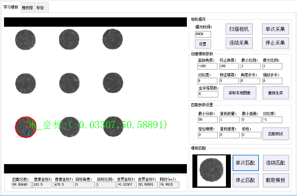
(3) How to Match Shape
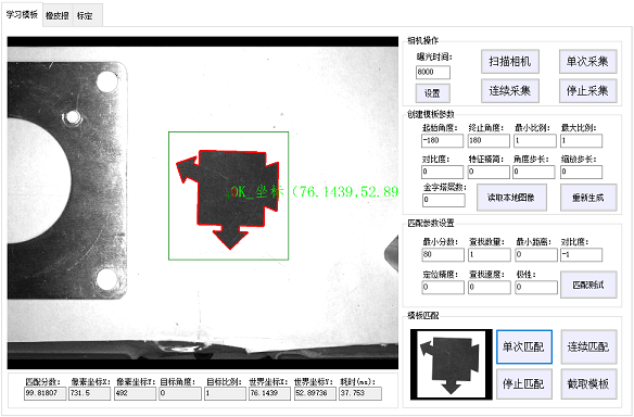
A. Operation Steps
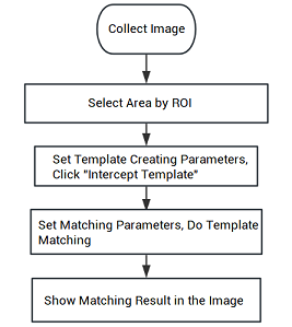
B. Relative Functions' Codes
/************************************************************************************
'Task No.: /
'Function of this function: collect image by camera
'Input: /
'Output: /
'Returned Value: /
**************************************************************************************/
public Image CameAcquisition()
{
float Temp = 0;
Image ImageBuff = null;
Zvision.CAM_COUNT(form.g_Handle, ref Cam_Num);
//select camera
Zvision.CAM_SEL(form.g_Handle, 0);
//collect one image
Zvision.CAM_TRIGGER(form.g_Handle);
//update belt position
zauxBrr = zmcaux.ZAux_Direct_GetMpos(form.g_Handle, form.ConveyorAxisId, ref Temp);
form.BeltMpos = Temp;
//get collected image from camera buffer
Zvision.CAM_GET(form.g_Handle, grabimg, 0);
//convert RGB to gray
Zvision.ZV_RGBTOGRAY(form.g_Handle, grabimg, grabimg);
//clear latch data
Zvision.ZV_LATCHCLEAR(form.g_Handle, 0);
//set the latch size as image showing control’s size
Zvision.ZV_LATCHSETSIZE(form.g_Handle, 0, Convert.ToUInt32(ImgShow1.Width), Convert.ToUInt32(ImgShow1.Height));
//get the image in the latch
ImgShow1.Image = Zvision.ZV_LATCH(form.g_Handle, grabimg, 0);
//export obtained image information
return ImgShow1.Image;
}
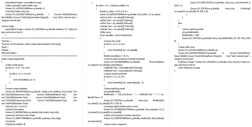
...... (remain, please refer to below Image)
