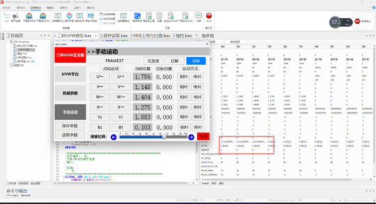


Zmotion UVW Alignment Platform Application
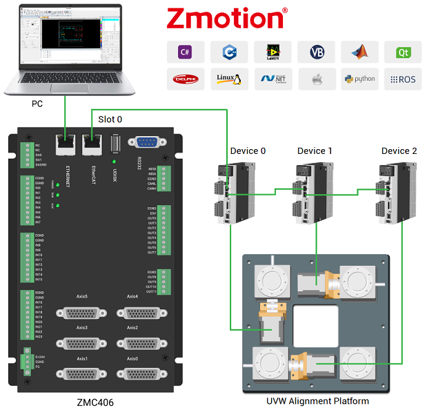
For UVW alignment platform, Zmotion Technology ZMC4XX motion controller supports 3-axis UVW with PPR and PRP structures, that is, joint-axis U + joint-axis V + joint-axis W. It downloads the edited program into controller by the way of offline (or real-time send commands to operate, watch the state by PC), and it can use HMI teaching method to edit needed motion trajectory.
--Which ZMC4XX Controller Used--
ZMC406 | Multi-Axis High-Performance EtherCAT Motion Controller
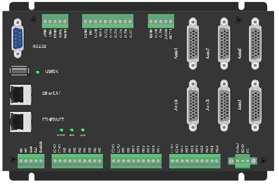
*Axis: 6 Axes (up to 32 axes by expansion module)
*IO & AIO: 24 IN & 12 OUT, 2 AD & 2DA
*Interfaces: EtherCAT, EtherNET, RS232, CAN, USB...
*Basic Functions: linear interpolation, any circular interpolation, space arc, helical interpolation, electronic cam, electronic gear, synchronous follow, etc.
*Development:
A. ZDevelop (RTSys): PLC & Basic & HMI
ZDevelop is one software to program & compile & debug. There are serial ports, EtherNET, PCI, LOCAL to build the connection with controller. While using below PC languages, it also can be connected to controller at the same time for debugging.
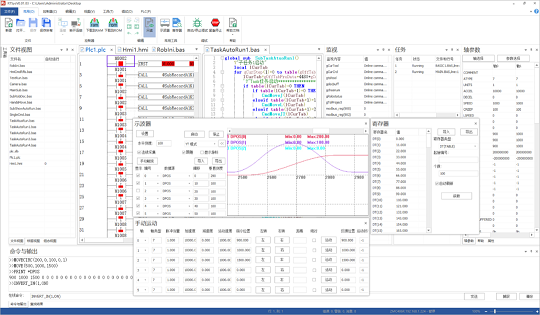
Support Chinese & English
B. PC API Programming: C#, C++, LabVIEW, Matlab, Qt, Linux, VB.Net, Python...
More Parameters & More Details, please refer to "ZMC406 EtherCAT Motion Control User Manual".
--Why ZMC Motion Controller, Not PCI Motion Control Card--
*no need to use slot: more stable
*MINI PC / ARM IPC: lower cost
*ZMC can be as wiring board: less space
*run program in parallel: only simple interaction with PC is needed
--Video Help--

1. What is UVW Alignment Platform
(1) UVW Platform Definition
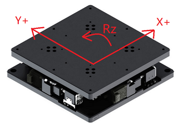
UVW platform is also called "XXY platform" or "XYR alignment platform". It can be known it is one 3-axis parallel motion structure, and mainly for high-precision alignment devices.
It controls these three linear axes' parallel motion to do rotation (take any one plane point as the center) and do parallel motion in any direction. Then, this kind of design becomes one core technology in industrial automation, and it extremely suits to alignment with high-precision.
(2) UVW Platform Applications & Advantages
UVW platform can be used together with vision CCD correction system to achieve high-precision correction. Generally, the precision of repeated positioning can be up to ±1μm.
Compared to xyθ platform, UVW control precision is higher, and UVW platform is more flexible:
--Higher Precision--
UVW can select one any point in the plane as the center to do rotation, but the center of xyθ platform must be fixed at one certain place on the plane and must move with the platform.
--More Flexible--
UVW platform needs one absolute coordinate system as the reference system, but xyθ platform takes the system that follows with the plane as the reference.
UVW Platform Work Mode:
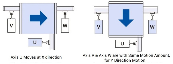

According to its design and above advantages, UVW platform can be mainly applied in PCB and semi-conductor industries, like, exposure machine, silk printer, laminating machine, etc. In these solutions, UVW platform matches with machine vision system to realize high-precision alignment function, then production efficiency and product quality are promoted.
In a short, UVW platform now is one important part of modern industrial automation because of high-precision, excellent flexibility, and wide applications.
(3) UVW Platform Structures: PPR VS PRP
These two structures mainly differ from “structure type” and “application feature”.
--Structure Type--
PPR and PRP represent different designs of UVW platform. Both are common types, but in aspects of specific mechanical layout, motion axes configuration, joint connection method, they are different. Then, all these differences make different performances in rigidity, stability, precision, etc.
--Application Feature--
PPR UVW Platform: focus on stability and precision, suit to high precision and stable motion applications.
PRP UVW Platform: suit to “more flexible & more complex motion mode” applications.
2. Zmotion UVW Robotic Arm Model
There are 3 common robot models based on UVW platform motion control algorithm, FRAME 33, FRAME 34, and FRAME 37.
And they correspond to two structure types (PRP, PPR) and two coordinate system directions (XYY, XXY) for single-axis linear motion, two-axis linear interpolation, two-axis circular interpolation, space arc, and other complex motions.
(1) FRAME 33 | UVW Alignment Platform (PRP Structure - XYY / XXY)
Principle: in one plane, there are three drive axes, move them to meet positioning requirement (below graphics: take the initial position after platform homing as the base reference).
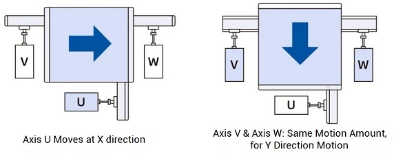

A. Determine Motor Direction & Angle Range
For virtual XY, it meets "right-hand rule", namely, angle forward direction and virtual XY. But for actual motor axes, no “direction” requirement. It only needs filling in structural parameters according to your actual situation.
B. Save Robot Structural Parameters into TABLE Register
While building robotic arm connection, please fill in below structural parameters (FRAME 33 Model) in sequence to TABLE array.
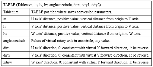
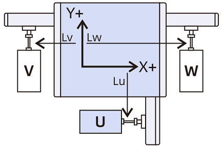
It saves robotic arm structural parameters into Table in order, starting from distance parameters of axis U, axis V, axis W, pulses of virtual rotate axis in one circle, directions of axis U, axis V, axis W.
TABLE (Tablenum, lu, lv, lw, angleonecircle, diru, dirv, zdirw)
Routine: fill in Frame required mechanical parameters starting from TABLE(100).
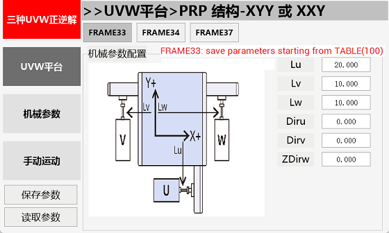
C. Set Joint-Axis & Virtual-Axis Parameters
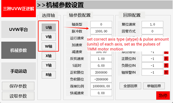
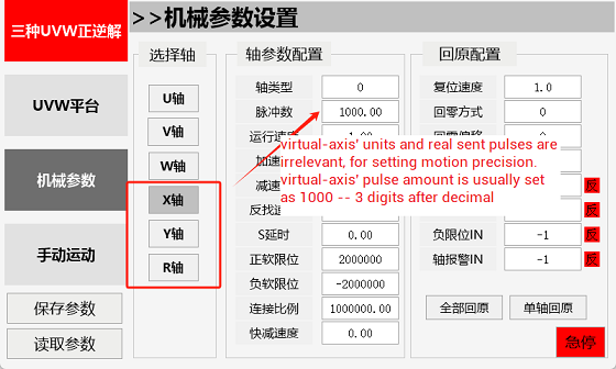
Each axis' axis type and pulse amount (units) must be set correctly, the pulses in 1mm motor motion. For the virtual axis, its units has no relevant with real sending pulses, it is used to set motion precision, usually virtual-axis pulse amount is set as 1000, which means the precision can be 3 digits after decimal.
D. Confirm Robotic Arm Origin Position
For FRAME 33, please make sure VW axes are horizontal. That is, any point in the plane can be as "origin", then it only needs to set correct structural parameters.
E. Build Robot Connection (Forward / Inverse)
--Forward Kinematics--
For FRAME33 model, at first, save parameters into TABLE starting from one certain Table No., then, select corresponding model's axis list, using CONNREFRAME command to build the forward kinematics mode.
During building, please refer to "CONNREFRAME" command through ZBasic Manual.
'save parameters into TABLE array starting from TableNum.
TABLE(TableNum, lu, lv, lw, angleonecircle, diru, dirv, zdirw)
'select axes
BASE(Viraxis_x, Viraxis_y,Viraxis_v)
'build robot forward kinematics connection
CONNREFRAME(33,tablenum, Axis_a,Axis_b,Axis_c)

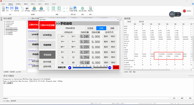
After connection, virtual axis MTYPE (current motion type) will be shown as 34. At this time, only joint-axis can be operated in joint coordinate system to adjust robotic arm attitude. For manual motion, open ZDevelop, click "Tool"--"Manual", then in "manual" window, select joint axes No. (here, axis 0 -- axis U, axis 1 -- axis V, axis 2 -- axis W) to do point motion or inch motion. At the same time, virtual-axis will automatically calculate the position of end working point in Cartesian coordinate system.
--Inverse Kinematics--
For FRAME33 model, at first, save parameters into TABLE starting from one certain Table No., then, select corresponding model's axis list, using CONNFRAME command to build the inverse kinematics mode.
During building, please refer to "CONNFRAME" command through ZBasic Manual.
'save parameters into TABLE array starting from TableNum.
TABLE(TableNum,lu,lv,lw,angleonecircle,diru,dirv,zdirw)
'select axes
BASE(Axis_a,Axis_b,Axis_c)
'build robot inverse kinematics connection
CONNFRAME(33,tablenum, Viraxis_x, Viraxis_y,Viraxis_v)

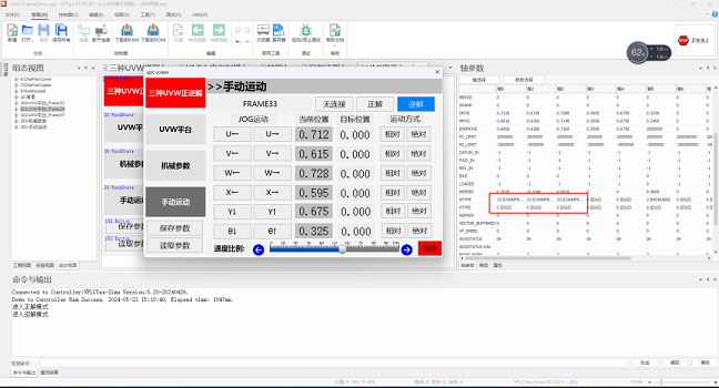
After connection, virtual axis MTYPE (current motion type) will be shown as 33. At this time, only virtual-axis can be operated by processing commands, and edited motion trajectory will be moved in Cartesian coordinate system (here, virtual axes are axis 3, axis 4, axis 5), at the same time, joint-axis will automatically calculate how to do joint motion in the joint coordinate system. For the "manual motion", same as virtual-axis operation methods.
(2) FRAME 34 | UVW Alignment Platform (PPR Structure - XXY)
A. Determine Motor Direction & Angle Range
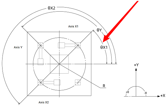
For virtual XY, it meets "right-hand rule", namely, angle forward direction and virtual XY. But for actual motor axes, no “direction” requirement. It only needs filling in structural parameters according to your actual situation.
B. Save Robot Structural Parameters into TABLE Register
While building robotic arm connection, please fill in below structural parameters (FRAME 34 Model) in sequence to TABLE array.
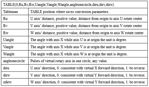
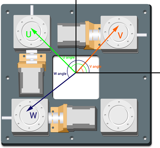
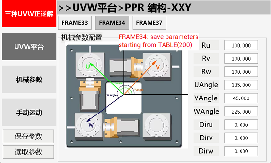
It saves robotic arm structural parameters into Table in order, starting from TableNum, parameters in order are distance parameters of axis U, axis V, axis W, angles with axis X while axis U & axis V & axis W at origin, pulses of virtual rotate axis in one circle, directions of axis U, axis V, axis W.
TABLE(TableNum,Ru,Rv,Rw,Uangle,Vangle,Wangle,angleonecircle,diru,dirv,dirw)
C. Set Joint-Axis & Virtual-Axis Parameters
Each axis' axis type and pulse amount (units) must be set correctly, the pulses in 1° motor motion. For the virtual axis, its units has no relevant with real sending pulses, it is used to set motion precision, usually virtual-axis pulse amount is set as 1000, which means the precision can be 3 digits after decimal.
D. Confirm Robotic Arm Origin Position
For FRAME 34, please make sure VW axes are horizontal, and they should be parallel to axis X, U is parallel to Y. That is, any point in the plane can be as "origin", then it only needs to set correct structural parameters.
E. Build Robot Connection (Forward / Inverse)
--Forward Kinematics--
For FRAME34 model, at first, save parameters into TABLE starting from one certain Table No., then, select corresponding model's axis list, using CONNREFRAME command to build the forward kinematics mode.
During building, please refer to "CONNREFRAME" command through ZBasic Manual.
'save parameters into TABLE array starting from TableNum.
TABLE(TableNum,Ru,Rv,Rw,Uangle,Vangle,Wangle,angleonecircle,diru,dirv,dirw)
'select axes
BASE(Viraxis_x, Viraxis_y,Viraxis_v)
'build robot forward kinematics connection
CONNREFRAME(34,tablenum, Axis_a,Axis_b,Axis_c)

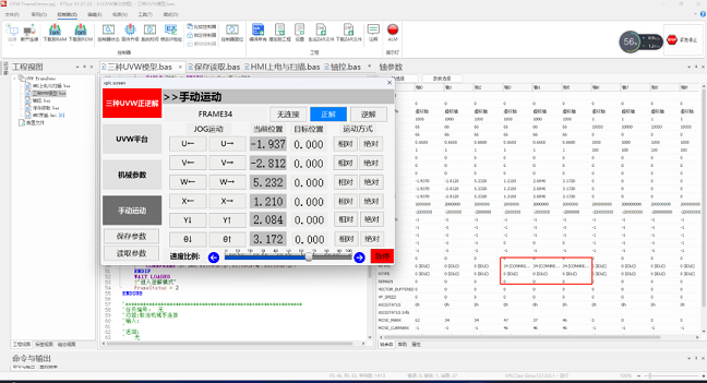
After connection, virtual axis MTYPE (current motion type) will be shown as 34. At this time, only joint-axis can be operated in joint coordinate system to adjust robotic arm attitude. For manual motion, open ZDevelop, click "Tool"--"Manual", then in "manual" window, select joint axes No. (here, axis 0 -- axis U, axis 1 -- axis V, axis 2 -- axis W) to do point motion or inch motion. At the same time, virtual-axis will automatically calculate the position of end working point in Cartesian coordinate system.
--Inverse Kinematics--
For FRAME34 model, at first, save parameters into TABLE starting from one certain Table No., then, select corresponding model's axis list, using CONNFRAME command to build the inverse kinematics mode.
During building, please refer to "CONNFRAME" command through ZBasic Manual.
'save parameters into TABLE array starting from TableNum.
TABLE(TableNum,Ru,Rv,Rw,Uangle,Vangle,Wangle,angleonecircle,diru,dirv,dirw)
'select axes
BASE(Axis_a,Axis_b,Axis_c)
'build robot inverse kinematics connection
CONNFRAME(34,tablenum, Viraxis_x, Viraxis_y,Viraxis_v)

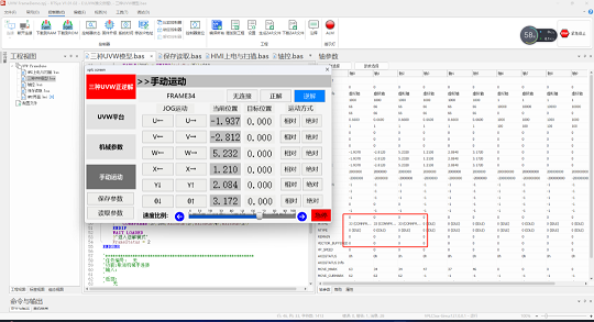
After connection, virtual axis MTYPE (current motion type) will be shown as 33. At this time, only virtual-axis can be operated by processing commands, and edited motion trajectory will be moved in Cartesian coordinate system (here, virtual axes are axis 3, axis 4, axis 5), at the same time, joint-axis will automatically calculate how to do joint motion in the joint coordinate system. For the "manual motion", same as virtual-axis operation methods.
(3) FRAME 37 | UVW Alignment Platform (PRP Structure - YYX)
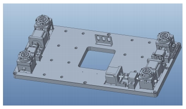
A. Determine Motor Direction & Angle Range
For virtual XY, it meets "right-hand rule", namely, angle forward direction and virtual XY. But for actual motor axes, no “direction” requirement. It only needs filling in structural parameters according to your actual situation.
B. Save Robot Structural Parameters into TABLE Register
While building robotic arm connection, please fill in below structural parameters (FRAME 37 Model) in sequence to TABLE array.
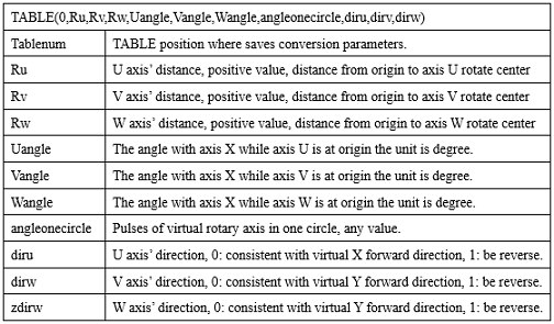
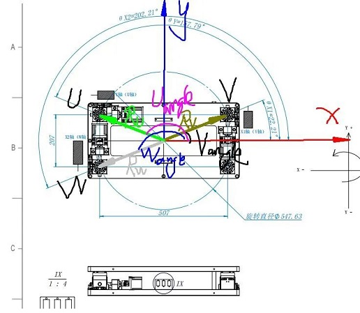
It saves robotic arm structural parameters into Table in order, starting from TableNum, parameters in order are distance parameters of axis U, axis V, axis W, angles with axis X while axis U & axis V & axis W at origin, pulses of virtual rotate axis in one circle, directions of axis U, axis V, axis W.
TABLE(TableNum,Ru,Rv,Rw,Uangle,Vangle,Wangle,angleonecircle,diru,dirv,dirw).
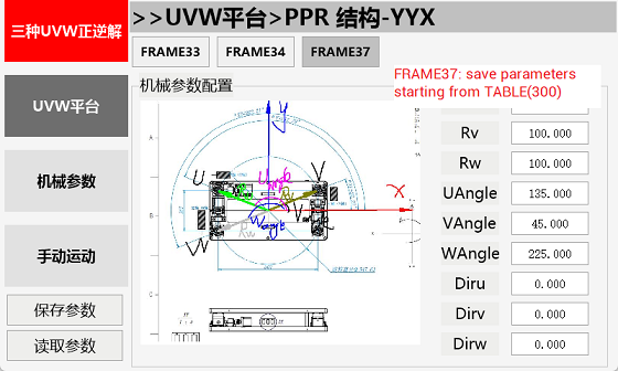
C. Set Joint-Axis & Virtual-Axis Parameters
Each axis' axis type and pulse amount (units) must be set correctly, the pulses in 1° motor motion. For the virtual axis, its units has no relevant with real sending pulses, it is used to set motion precision, usually virtual-axis pulse amount is set as 1000, which means the precision can be 3 digits after decimal.
D. Confirm Robotic Arm Origin Position
For FRAME 37, please make sure VW axes are horizontal, and they should be parallel to axis X, U is parallel to Y. That is, any point in the plane can be as "origin", then it only needs to set correct structural parameters.
E. Build Robot Connection (Forward / Inverse)
--Forward Kinematics--
For FRAME37 model, at first, save parameters into TABLE starting from one certain Table No., then, select corresponding model's axis list, using CONNREFRAME command to build the forward kinematics mode.
During building, please refer to "CONNREFRAME" command through ZBasic Manual.
'save parameters into TABLE array starting from TableNum.
TABLE(TableNum,Ru,Rv,Rw,Uangle,Vangle,Wangle,angleonecircle,diru,dirv,dirw)
'select axes
BASE(Viraxis_x, Viraxis_y,Viraxis_v)
'build robot forward kinematics connection
CONNREFRAME(37,tablenum, Axis_a,Axis_b,Axis_c)

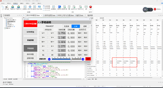
After connection, virtual axis MTYPE (current motion type) will be shown as 34. At this time, only joint-axis can be operated in joint coordinate system to adjust robotic arm attitude. For manual motion, open ZDevelop, click "Tool"--"Manual", then in "manual" window, select joint axes No. (here, axis 0 -- axis U, axis 1 -- axis V, axis 2 -- axis W) to do point motion or inch motion. At the same time, virtual-axis will automatically calculate the position of end working point in Cartesian coordinate system.
--Inverse Kinematics--
For FRAME37 model, at first, save parameters into TABLE starting from one certain Table No., then, select corresponding model's axis list, using CONNFRAME command to build the inverse kinematics mode.
During building, please refer to "CONNFRAME" command through ZBasic Manual.
'save parameters into TABLE array starting from TableNum.
TABLE(TableNum,Ru,Rv,Rw,Uangle,Vangle,Wangle,angleonecircle,diru,dirv,dirw)
'select axes
BASE(Axis_a,Axis_b,Axis_c)
'build robot inverse kinematics connection
CONNFRAME(37,tablenum, Viraxis_x, Viraxis_y,Viraxis_v)

After connection, virtual axis MTYPE (current motion type) will be shown as 33. At this time, only virtual-axis can be operated by processing commands, and edited motion trajectory will be moved in Cartesian coordinate system (here, virtual axes are axis 3, axis 4, axis 5), at the same time, joint-axis will automatically calculate how to do joint motion in the joint coordinate system. For the "manual motion", same as virtual-axis operation methods.
