

--XPLC006E Function Introduction--

XPLC006E
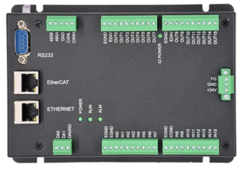
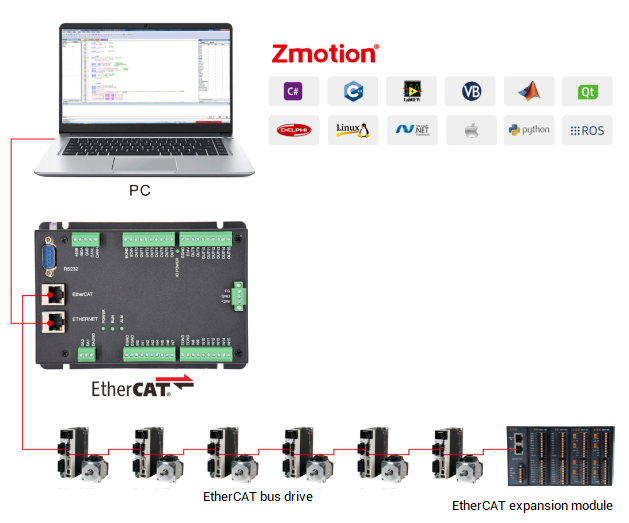
is a kind of multi-axis economical EtherCAT bus motion controller developed by ZMotion Technology, and XPLC series motion controllers can be applied in all kinds of occasions that need offline or online operation.

XPLC006E has 6 motor axes itself, and motion control of 12 axes at most can be achieved (including virtual axes). Also, it supports 12-axis linear interpolation, electronic cam, electronic gear, synchronous follow, virtual axis setting, etc.
In addition, XPLC006E cost-effective controller supports multi-task run synchronously. At the same time, it can do simulation on PC directly. There are several valid programming methods, such as, Basic / PLC ladder diagram / HMI configuration in ZDevelop software and commonly used upper computer software.
For PC upper computer API programming, following interfaces are supported: C#, C++, LabVIEW, VB, matlab, Qt, Linux, .Net, iMAC, Python, ROS, etc.

→Actually, according to different axis numbers, there are XPLC004E, XPLC006E and XPLC008E
There is one note: XPLC006E belongs to bus motion controller, which means it only supports EtherCAT bus axes, pulse axes and encoder axes are invalid. Then, it uses EtherCAT bus and drive to communication with refresh cycle of 1ms.
--XPLC864E2 Function Introduction--

Let's see
XPLC864E2
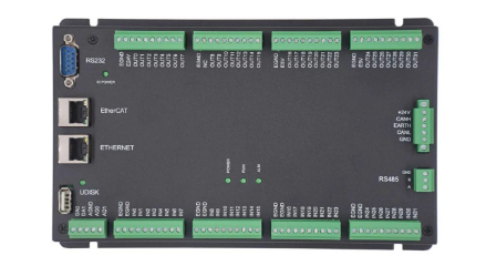
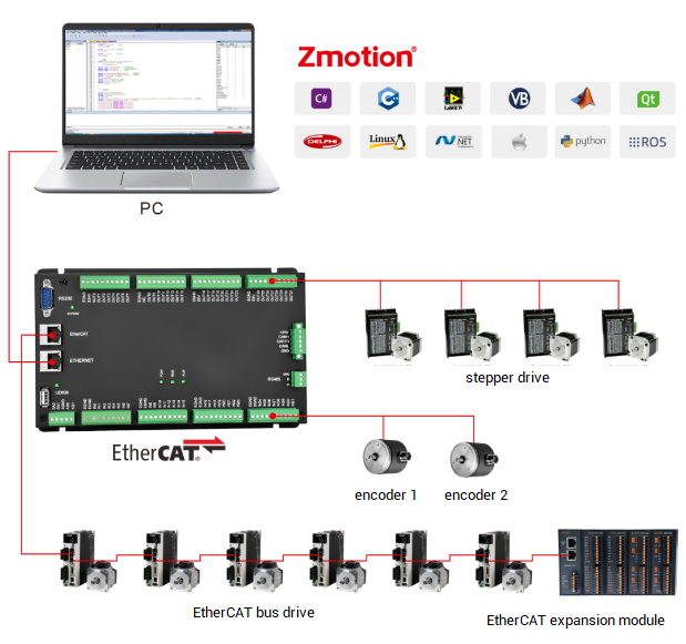
, it is upgraded on the basis of XPLC006E, which means, it supports all functions of XPLC006E mentioned above, and usages are basically the same. However, some resource spaces are better than XPLC006E. What's more, XPLC864E2 supports 32 inputs, 32 outputs, 2 ADs and 2 DAs in hardware level, pulse axis and bus axis can be hybrid used. The number of real axes is 8 totally. Except EtherCAT interface, in hardware of output, signal output of 8 axes in pulse direction can be configured, and be with 2 encoder inputs set by input configuration.
Same, XPLC864E2 supports PLC, Basic and HMI configuration programming methods. For PC upper computer API programming, following interfaces are supported: C#, C++, LabVIEW, VB, matlab, Qt, Linux, .Net, iMAC, Python, ROS, etc.


Let's begin!
Serial port and net port of XPLC006E EtherCAT motion controller use MODBUS Protocol, which means HMIs that support MODBUS communication protocol all can be connected to XPLC006E controller.
When the controller and the third party HMI do communication through MODBUS protocol, data need to be saved into MODBUS register to transfer. Also, select connection method with controller from serial port or net port, and there are 2 valid registers, bit register and word register.
Please note, the mapping relation of controller MODBUS address and HMI address of other manufacturers is different, therefore, clear relation between controller and HMI MODBUS register address before editing the program. Below shows some relative relation.
(1) Controller MODBUS address starts from 0, when does communication with WEINVIEW HMI, addresses all begin with 0, therefore, they are corresponding.
Controller MODBUS_BIT(0) relates to WEINVIEW HMI MODBUS_0X_0, Boolean type.
Controller MODBU_REG(0) relates to WEINVIEW HMI MODBUS_4X_0, Word-register type.
(2) When does communication with MCGS HMI, address starts from 1, there is no address 0. But controller address starts from 1, then HMI address should add one.
Controller MODBUS_BIT(0) relates to MCGS HMI MODBUS_0X_1, Boolean type.
Controller MODBUS_REG(0) relates to MCGS HMI MODBUS_4X_1, Word-register.

Select communication connection method according to communication interfaces on HMI and controller, there are serial port or net port connection. When build the communication connection between HMI and controller, HMI is master station, and controller is the slave station, then operate connection mainly in HMI station, relative serial port or net port parameters should be matched. For controller station, it only needs to provide parameters for communication. Followings describe net port and serial port communication parameters.
(1) Net-port Connection
Controller default IP address is "192.168.0.11", and net port is MODBUS slave station by default. IP address can be checked through "ZDevelop" -- "Controller State". What's more, IP can be modified by "IP_ADDRESS" instruction or in window, and modify once, it becomes valid all the time. In addition, controller includes 2 net port channels at least, the terminal No. is 502, which supports HMI MODBUS-TCP protocol connection.
Net-port Channel Number Checking:
Different controller models support different serial port channels and net port channels. It can be checked through entering "?*port" in "online and command", like below image. And when the number of channels is confirmed, then it indicates how many equipment can be connected for controller at the same time.

In the above image, Port (0-1) mean serial port channel, (2-9) mean net port channel, (10-15) mean customized net port communication channel and 20 means controller interconnection channel.
Different controllers support different communication channels. As mentioned before, controller has 2 net-port channels at least, therefore, it can connect 2 equipment at the same time through net port, such as, when connected tp upper computer program, then connect to ZDevelop software to watch online. In addition, 2 different devices can be connected through Router.
Through "?*port_status" in online command bar, check whether communication ports are used or not. If return value is 0, which means disconnection, if it is 1, which means connected.
The former two channels COM are serial port channels, and serial port always returns as 1. The third channel is net port channel, which is used to connect to ZDevelop.

For the current net port channel protocol, please use "PROTOCOL" instruction to return communication protocol of current channel, and then judge according to returned value in below form.
VAR1 = PROTOL (port)
port: channel No.

(2) Serial-port Connection
There are RS232 and RS485, and the default parameters are "Baud rate 38400, data bit 8, stop bit 1 and no parity". Serial port is default as MODBUS slave station, no need to modify when communicating with HMI, and it use "SETCOM" instruction to configure serial port parameters.
Note: serial parameters are not saved when power-off. When controller is powered on again, SETCOM parameters will return to default values. All serial ports' MODBUS protocol station No. (ADDRESS) of controller is 1-127, the default value is 1.
In addition, serial port parameters can be viewed through "Controller State" window, or send "?*SETCOM".

(1) Normal step:
→ Download program written in ZDevelop into controller.
→ HMI program written by relevant programming software is downloaded and saved in HMI.
→ After program is downloaded, choose serial port or net port to link HMI with controller for offline operation.
When communicating, there are several kinds of registers, such as, MODBUS_BIT (Boolean type), MODBUS_REG (16-bit integer), MODBUS_LONG (32-bit integer), MODBUS_IEEE (32-bit floating) and MODBUS_STRING (8-bit byte).
(2) Download Controller Program
Program of controller is programmed by ZDevelop software and downloaded into controller.

(3) Download HMI Program
Program of WEINVIEW HMI is programmed by EasyBuilder software, for programming method, please refer to manuals provided by WEINVIEW, after programming, then open “system parameter setting” window, please see below.

A. Add equipment to be connected with HMI
Device list shows local HMI and local device, if there is local device, please double click this line, if there isn’t, click “new build device/servicer” like the below, then device property window will jump.

B. Set device property
Like below, select device type, first select MODBUS IDA communication protocol, then select according to actual connection method of HMI and controller.
There is different between serial port communication and net port communication, please see following for details.

a- If connects through serial port:
Device type: select mode MODBUS RTU (Zero-based Addressing)
Interface type: select serial port (RS485/RS232)
COM: Baud rate matched with communication port and other parameters, see below, now, the parameter must be same as port parameter connected on controller. After setting, confirm system parameter setting window is closed.

b- If connects through net port:
Device type: select mode MODBUS RTU (Zero-based Addressing), interface type will changed into Ethernet automatically.
IP: fill the IP address and port number of controller that is to be connected currently. See below:
After setting, confirm that system parameter setting window is closed.

After system parameters are set, compile written configuration program, click “编译”, open the window.

Click right corner (Start to compile) “开始编译”, if compiling successfully, there will print information, and (Start to compile) “开始编译” will become (compile) “编译”, if program is incorrect, the window will print error information, then need to modify program until it compile successfully.

If it is successfully, connect HMI to PC and download the program.

Click “download”, program will be downloaded into HMI through Ethernet, and after downloading, the program has been written into HMI, now, disconnect HMI and PC.
C. HMI communicates with controller
After the program on the controller side is successfully downloaded to the controller, and the program on the HMI side is successfully downloaded to the HMI, it can be disconnected from the PC, and connect to HMI and controller physically. At this time, HMI and the controller can communicate with each other. If fails to communicate, please check HMI communication parameters configuration in the former step.
D. Controller and HMI simulate offline
If there is no controller or HMI, it can use simulator. The ZDevelop program is downloaded to the simulator and only supports network port connection. According to the above steps, when setting the system parameters of the EasyBuilder software, select the device type as MODBUS IDA—MODBUS TCP/ IP (Zero-based Addressing), fill in the IP address of the simulator IP: 127.0.0.1, select "Online Simulation" to connect the controller program and the configuration program for simulation.

After clicking the online simulation, the compilation will start automatically, and the compilation result will correctly open the following HMI simulation interface, which can be operated at this time. If the compilation is unsuccessful, an error message will be reported.
Touch screen simulation interface:

(1) Material Preparations:
One computer: for program development
One controller: XPLC864E, for linear and plane circular interpolations
One 24V DC power supply: controller uses 24V DC power supply
Two sets of bus drive + motor (step drive + motor): depend on axes
One WEINVIEW HMI: human-machine interaction
Several controller wiring terminals
Several net cables
Several connecting lines.
(2) Project Configuration
Registers D used in this project are MODBUS_IEEE.
→ Task Resources Configuration: this occupies three tasks.
Task 0: main cycle, scan external input signals circularly to decide switch-on of other tasks.
Task 1: it is opened by task 0, before processing, use task 1 firstly to execute homing program. When homing is done, task 1 will be used to process program.
Task 2: it is opened by task 0, and it is used for manual motion.
See below image, MODBUS register values can be checked in bulk through “ZDevelop” – “Register” window.

(3) Application Program
A. WEINVIEW HMI Program
Edit program through configuration program software provided by HMI manufacturer, and HMI communicate with controller through MODBUS, the element property setting relates to MODBUS register address. Press element, relative MODBUS register address value can be modified, then transfer to controller. Then program interface is below.

B. Controller Program
Program interface and program of controller:

Controller side scans changes of MODBUS register values through WHILE to decide whether relative programs are executed or not.

C. Application Program Running Effect
-- resultant interpolation trajectory of axis position under XY curve mode --

-- resultant interpolation trajectory under XY mode --
