

--XPLC006E Function Introduction--

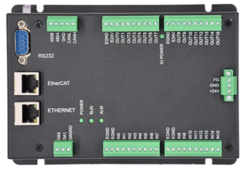
XPLC006E
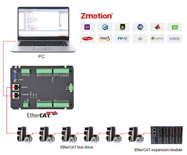
is a kind of multi-axis economical EtherCAT bus motion controller developed by ZMotion Technology, and XPLC series motion controllers can be applied in all kinds of occasions that need offline or online operation.

XPLC006E has 6 motor axes itself, and motion control of 12 axes at most can be achieved (including virtual axes). Also, it supports 12-axis linear interpolation, electronic cam, electronic gear, synchronous follow, virtual axis setting, etc.
In addition, XPLC006E cost-effective controller supports multi-task run synchronously. At the same time, it can do simulation on PC directly. There are several valid programming methods, such as, Basic / PLC ladder diagram / HMI configuration in ZDevelop software and commonly used upper computer software.
For PC upper computer API programming, following interfaces are supported: C#, C++, LabVIEW, VB, matlab, Qt, Linux, .Net, iMAC, Python, ROS, etc.

→Actually, according to different axis numbers, there are XPLC004E, XPLC006E and XPLC008E
There is one note: XPLC006E belongs to bus motion controller, which means it only supports EtherCAT bus axes, pulse axes and encoder axes are invalid. Then, it uses EtherCAT bus and drive to communication with refresh cycle of 1ms.
--XPLC864E2 Function Introduction--

Let's see
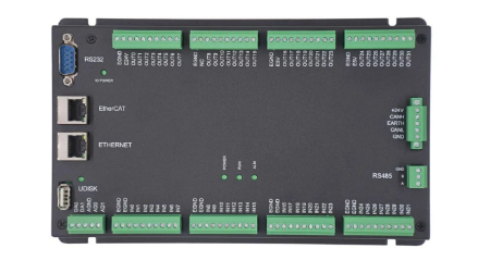
XPLC864E2
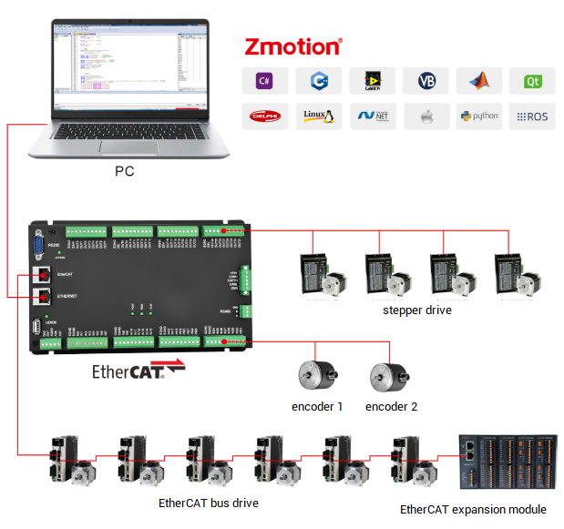
, it is upgraded on the basis of XPLC006E, which means, it supports all functions of XPLC006E mentioned above, and usages are basically the same. However, some resource spaces are better than XPLC006E. What's more, XPLC864E2 supports 32 inputs, 32 outputs, 2 ADs and 2 DAs in hardware level, pulse axis and bus axis can be hybrid used. The number of real axes is 8 totally. Except EtherCAT interface, in hardware of output, signal output of 8 axes in pulse direction can be configured, and be with 2 encoder inputs set by input configuration.
Same, XPLC864E2 supports PLC, Basic and HMI configuration programming methods. For PC upper computer API programming, following interfaces are supported: C#, C++, LabVIEW, VB, matlab, Qt, Linux, .Net, iMAC, Python, ROS, etc.


Let's begin!
Except sending motion instructions, obviously we also need to assign axis motion speed, the speed parameter also can be called as axis parameter. Axis parameters are needed for axis motion. There are some commonly used axis parameters, such as, speed, acceleration, deceleration, pulse amount, axis type, etc.
(1) BASE -- axis selection / axis group selection
BASE instruction is used to select corresponding axis No. to do parameter configuration and motion control. Each process has its own BASE basic axis group, and each program can be assigned independently.
When setting axis parameters or running axes, use BASE instruction to select relative axis No. at the beginning, and the first axis is the master axis by default.
If axis No. is not assigned, the first axis
Grammar: BASE (axis 0, axis 1, axis 2, ...)
Example:

In multi-axis occasions, before sending motion instructions, it is better to assign the axis to be received the current instruction through BASE. For example, in above case, set axis Y to move 100 units, if MOVE(100) is set to axis X, which means the motion is wrong, the correct is below.

(2) ATYPE -- axis type
ATYPE is the definition of the axis function. Usually, the axis function is defined when the program is initialized. It can be defined as non-encoded feedback type, encoder feedback type, encoder + Z signal feedback type, EtherCAT bus type, etc. If the ATYPE setting is abnormal, the axis will run abnormally or the program will not run normally.
Grammar: ATYPE=type value or ATYPE (axis No.)=type value
The following form is a detailed description of the axis type ATYPE definition.
ATYPE=1/7, axis is the pulse output type.
ATYPE=4/5, axis is pulse output + encoder input type.
ATYPE=3/6, axis is the encoder input type.
ATYPE=65/66/67, axis is the type of EtherCAT bus axis.
ATYPE=50/51/52, axis is the type of RTEX bus axis.

(3) UNITS -- pulse amount
In the motion control device, when the mechanical structure is determined, the transmission relationship between the motor and the mechanical device is fixed, and the mechanical displacement generated by the motor per revolution is also fixed. Pulse amount "UNITS" is the number of pulses corresponding to each unit, which can be unit distance, unit angle, etc., and supports 5 decimal places.
The controller uses UNITS as the basic unit, and the target position, speed, acceleration and deceleration of the movement are all calculated and executed with UNITS as the basic unit. After the UNITS is modified, the target position, speed, acceleration and deceleration, etc. will change along with UNITS proportionally.
Grammar: UNITS=variable or UNITS(axis number)=variable
Example: UNITS=10000
The UNITS reference calculation methods for several common mechanical transmissions are shown in the form below.

If the pulse amount is set as 1000, and the speed SPEED takes the set pulse amount as the unit, then pulses are sent to the actuator every second according to the current set speed value*1000.
At this time, if the distance parameter of the linear motion command is written as 2, then 2*1000 pulses will be sent, and how many angles 2000 pulses can make the motor turn, please refer to the setting of the number of pulses per revolution of the motor (the number of pulses required for one revolution of the motor) , if the number of pulses per revolution of the motor is 10000, then 2000 pulses can make the motor rotate 72°, so that the actual movement distance of the motion command can be converted.
The above is the setting method of the pulse equivalent "UNITS". In a word, the number of pulses per circle of the motor must be checked before setting, and then set in combination with the characteristics of the mechanical structure.
Generally speaking, the number of pulses per circle of a stepping motor is small, but of a servo motor is relatively large, it takes hundreds of thousands or millions of pulses to drive the motor to make one circle. Therefore, the precision of the servo is relatively high, then the cost is also higher.
(4) SPEED -- motion speed
The speed at which the axis is running, in UNITS/s.
When a single axis is in motion, the acceleration of the motion speed is the speed of the single axis, and when multiple axes are in motion, it is the composite vector speed of the interpolation motion.
After SPEED is modified, it will take effect immediately, and dynamic shifting can be realized. Smooth shifting can also use the SPEED_RATIO command to adjust the magnification.
Grammar: SPEED=variable or SPEED (axis number) = variable
Example: SPEED=100 'The number of pulses sent per second is 100*UNITS
(5) ACCEL -- acceleration
When the axis is running from the initial speed to the target speed, the speed value reached per second, the unit is UNITS/s^2, the greater the acceleration, the shorter the time to reach the target speed.
When a single axis is moving, the acceleration of the motion speed is the acceleration of the single axis, and when the multi-axis is moving, the acceleration of the interpolation motion is the acceleration of the multi-axis vector synthesis.
Grammar: ACCEL=variable or ACCEL(axis number)=variable
Example: ACCEL =1000 'The acceleration is 1000 UNITS/s^2
(6) DECEL -- deceleration
When the axis is running from the running speed to the stop, the speed value reached per second, the unit is UNITS/s^2, the greater the deceleration, the shorter the time to reach the stop speed.
When a single axis is moving, the deceleration of the motion speed is the deceleration of the single axis, and when the multi-axis is moving, the deceleration of the interpolation motion is the deceleration of the multi-axis vector synthesis.
Grammar: DECEL=variable or DECEL(axis number)=variable
(7) POS -- demand position
DPOS means the target position or required position of the axis, and with UNITS as the unit. It is used as the position reference of the current axis. The value increases when moving forward, and decreases when the axis moves reversely. And DPOS will be cleared automatically when homing finished, then DPOS (0) indicates that at the origin position, if the value of DPOS is changed manually, it will be automatically converted to OFFPOS offset, and the motor will not be moved.
The range of DPOS is limited by the positive and negative software limits. If the set DPOS is exceeded, it will automatically alarm and stop the axis movement.
(8) MPOS -- measurement position
MPSO means feedback position of the axis, this parameter is valid only after the feedback is connected. Generally, there is an encoder measurement feedback. If there is no feedback, the value of MPOS will automatically copy the value of DPOS, which has no reference value. If you manually change the value of DPOS, it will be automatically converted to OFFPOS offset.
Generally, there is a certain error between MPOS and DPOS. The better the servo performance is, the smaller the error is. Theoretically, it cannot be completely eliminated, but it can be very close.
Correspondingly, SPEED is the target speed, and MSPEED is the real motion speed measured by the encoder.
Note that after returning to zero in partial zero-return mode, DPOS will be automatically cleared, but MPOS will not, and MPOS needs to be manually cleared, otherwise it may cause errors in subsequent movements.
(9) AXIS -- assigned No.
From above, we know that the meaning of SPPED(1)=1000 is to specify the movement speed of axis 1 as 1000, and SPEED=1000 because the axis number is not specified, and the first axis of BASE is set by default.
But the parentheses of commands such as MOVE(100) are motion parameters, and the axis number cannot be filled in. We can write this parameter as MOVE(100) AXIS(0), and specify which axis the current parameter is set to by adding the AXIS command.

(10) Axis parameters

Under these parameters, the software oscilloscope samples the waveforms of different parameters changing with time, as shown in the figure below. The acceleration and deceleration can be reflected through the speed curve.
DPOS(0) and MSPEED(0) are the displacement trajectory and velocity trajectory of axis 0 respectively
DPOS(1) and MSPEED(1) are the displacement trajectory and velocity trajectory of axis 1 respectively.

(1) Single-axis motion
Each axis is independent for single-axis motion, which means each is controlled by own motion parameters, no relationships with other axes. There are several types of single-axis motion, single-axis inching motion, single-axis jogging motion, single-axis continuous motion and homing motion.
inching motion
Limited pulses will be sent to single-axis through MOVE instruction, such as, MOVE(100), and axis will decelerate and stop when 100 finished.
JOG motion
JOG motion is a simple single-axis motion, which is controlled by external input signal and moves at assigned speed.
JOG motion needs to connect with external input signal, use FWD_JOG instruction to map JOG input in positive direction, and use REV_JOG instruction to map JOG input in negative direction. When there is input signal, it moves at the speed of "JOGSPEED" instruction, if no input, it will stop immediately.
Please note when mapped JOG switch, for the controller whose OFF signal is valid, electricity level must be inverted through "INVERT_IN". For example, OFF signals of ZMC series controllers are valid, if the level is not inverted, controller will judge there is input even if the signal is OFF when connected, then axis motion will stop immediately. For the models of valid ON, no need to invert.
A. jog routine

B. running effects.
when input 0 has signal, axis 0 moves in positive direction, the speed is 50.
when input 1 has signal, axis 0 moves in negative direction, the speed is 50.
when input 0 and input 1 both have signals, axis 0 moves in positive direction.

continuous motion
Controller has specific continuous motion instructions, controller sends pulse continuously and control axes do continuous motion at assigned speed and direction. The commonly used instruction is VMOVE, move continuously at the speed of "SPEED", now, stop axes motion through "CANCEL" or "RAPIDSTOP".
For VMOVE, it can select forward or inverse. VMOVE(1) means forward, VMOVE(-1) means negative, and the next VMOVE will automatically replace the former VMOVE instruction.
Continuous motion routine:

(2) Interpolation Motion
Interpolation is a real-time data densification process. The controller calculates the data according to the given motion information, continuously calculates the feed commands of each coordinate axis participating in the interpolation motion, and then drives the respective execution components to generate coordinate motion so that the controlled mechanical parts move at desired routes and speeds.
The two most common interpolation methods are MOVE linear interpolation and MOVECIRC circular interpolation. Interpolation movement requires at least two axes. When performing interpolation movement, the planned axes are mapped to the corresponding machine coordinate system. The motion controller controls the movement of each axis according to the coordinate mapping relationship to achieve the required movement trajectory.
For interpolation motion, the special is all axes in interpolation start and stop at the same time, and use motion parameters (speed, acceleration, etc.) of master axes, the master axis is the first axis selected by BASE instruction.
The interpolation motion command will be stored in the motion buffer of the main axis, and will not enter the motion buffer of the slave axis, and then the commands will be taken out from the motion buffer of the main axis to execute until the interpolation motion is completely executed.
linear interpolation - Move
Single-axis linear motion or multi-axis linear interpolation motion, relative motion distance. Absolute movement uses MOVEABS instruction, and SP movement uses MOVESP instruction.
The interpolation motion parameters adopt the main axes parameters, and the interpolation motion is buffered in the motion buffer of the master axis.
Grammar: MOVE(distance1 [,distance2 [,distance3 [,distance4...]]])
Example: Two-axis linear interpolation

linear interpolation resultant trajectory:
the start point and end point are (100,0), processing in anticlockwise.

plane circular interpolation - MOVECIRC
Two-axis circular interpolation, the starting point, the end point, and the center of the circle draw an arc, the starting point uses the current coordinates of the axes, and moves relative to each other. Absolute circular interpolation uses the MOVECIRCABS instruction. SP circular interpolation uses the MOVECIRCSP instruction.
The MOVECIRC2 instruction draws an arc using the current point, intermediate point, and end point.
The circular interpolation command is applicable to two-axis motion.
Grammar: MOVECIRC(end1, end2, centre1, centre2, direction)
(end1, end2): end point coordinates
(centre1, centre2): coordinates of the center of the circle
direction: direction, 0-anticlockwise, 1-clockwise.
When the coordinates of the start point and the end point are the same, a full circle is drawn. For arc-related commands, ensure that the given center and end point coordinates together with the current point can correctly describe an arc, otherwise an error will be reported and the arc cannot be drawn, and error code is 1006.
For example:

Circular interpolation resultant trajectory:

space arc - MSPHERICAL
Space arc interpolation movement, relative movement, the starting point of the space arc is the current point, and the second and third points are specified by the command. Absolute movement uses the MSPHERICALABS instruction, and continuous interpolation movement with custom speed can use the instruction with the SP suffix.
Grammar:
MSPHERICAL(end1,end2,end3,centre1,centre2,centre3,mode[,distance4][,distance5])
(end1, end2, end3): the coordinates of the second point
(centre1, centre2, centre3): the coordinates of the third point
mode: specify the meaning of the first two coordinate points, as shown in the following form
distane4: The function of the fourth axis spiral, specify the relative distance of the fourth axis, this axis does not participate in the speed calculation
distane5: The function of the fifth axis spiral, specify the relative distance of the fifth axis, this axis does not participate in the speed calculation table

for example:

mode 0: current point, middle point and end point, these three points determine the space circular.

mode 3: the current point, the center point and the end point determine the full circle.
MSPHERICAL(120,160,400,120,160,150,3) 'end point (120,160,400), center of circle (120,160,150), take the shortest arc (red part) first, and then walk the complete circle.

(3) Synchronization motion
Synchronous motion describes that the motion between different axes is linked, such as electronic gear, electronic cam, automatic cam, etc.
electronic gear
The electronic gear function is used for the connection of two axes. The main axis and the slave axis are connected according to a constant gear ratio. There is no need for physical gears, and the ratio of the electronic gear can be directly set by using instructions. Since it is realized by software, the electronic gear ratio can be subject to change.

The function of the electronic gear is realized by the instructions CONNECT and CONNPATH. One axis is connected to another axis according to a certain ratio for follow-up movement. And one motion instruction can drive the operation of two motors. By detecting the movement of the two motor axes, feedback the displacement deviation to the controller and obtain synchronous compensation, so that the displacement deviation between the two axes can be controlled within the allowable range of precision.
The electronic gear is connected to the number of pulses. For example, the connection ratio of the master and slave axes is 1:5, and one pulse is sent to the master axis, and 5 pulses are correspondingly sent to the slave axis.
The same point between CONNPATH and CONNECT: the usage syntax of the two is the same, the number of pulses is connected, and the effect of CONNPATH connected to the movement of a single axis is the same as that of CONNECT.
The difference between CONNPATH and CONNECT: CONNECT connects the target position of a single axis. CONNPATH is connected to the vector length of the interpolation axis. At this time, it needs to be connected to the main axis of the interpolation movement, and it cannot follow the interpolation movement when connected to the interpolation slave axis. CONNPATH tracks the vector length changes for XY interpolation, rather than tracking individual X or Y axes.
Grammar: CONNECT/CONNPATH (ratio, connected axis) AXIS (connected axis)
The connection ratio of the electronic gear: the ratio can be positive or negative, and it can be a decimal. The number of pulses is connected, and the ratio of UNITS of different axes should be considered. The ratio can be dynamically changed by repeatedly calling the CONNECT/CONNPATH command (keep the connection state after the connection is successful), and use the CANCEL or RAPIDSTOP command when canceling the connection.
→ Assume that the UNITS of the connecting axis 0 is 10, the UNITS of the connected axis 1 is 100, use CONNECT connection, the ratio ratio is 1, CONNECT(1,1) AXIS(0)
When axis 1 moves S1=100, axis 0 moves S0=S1*UNITS(1)*ratio/UNITS(0)=100*100*1/10, and the movement is 1000 at this time.
Example:

Axis 0 target position:
DPOS(0)=DPOS(1)*UNITS(1)*ratio/UNITS(0)=100*100*0.5/10=500.
The motion waveform is shown in the figure:

electronic cam
The function of the cam is to convert rotary motion into linear motion, including linear motion, swing, uniform motion and non-uniform motion. The electronic cam belongs to the multi-axis synchronous motion. This motion is based on the main axis plus one or more slave axis systems. It is developed on the basis of the mechanical cam. The electronic cam is mostly used for periodic curved motion occasions.
The electronic cam is a software system that simulates the mechanical cam by using the constructed cam curve to achieve the same relative motion between the cam axis and the main axis as the mechanical cam system. The controller controls the servo motor to simulate the function of the mechanical cam without additional installation. The mechanical structure of the cam is shown in the left figure below.
As shown in the figure on the right below, the mechanical cam can obtain a section of rotation angle and processing position trajectory according to the contour of the cam. Approaching the trajectory of the arc, the electronic cam directly loads the motion parameters of this segment of the trajectory into the motion command, and then the axis can be controlled to walk out of the target trajectory.

The electronic cam uses software to control the signal, and the motion curve can be changed by changing the relevant motion parameters of the program. The application flexibility is high, the work is reliable, the operation is simple, and there is no need to install additional mechanical components, so there is no wear and tear.
The cam command includes CAM cam table movement, CAMBOX follows the cam table movement, MOVELINK and MOVESLINK automatic cam movement.
Take the CAM cam table motion command as an example. Cam table motion is to store the track point of the cam motion in the form of data in the TABLE register area, then the CAM command calls the data motion of the TABLE table to form a motion track. The camshaft needs to be used in conjunction with other shafts to process smooth curves.
Two or more CAM instructions can use the same TABLE data area to operate at the same time. TBALE data needs to be set manually, the first data is the guide point, it is recommended to set it to 0.
After the cam table instruction moves the called TABLE data point, the cam motion ends, and when periodic execution is required, write the cam table instruction in the WHILE loop.
The meaning of the CAM command: determine the motion of the axis according to the data stored in the TABLE. These TABLE data values correspond to the position of the motion track, which is the absolute position relative to the starting point of the motion.
Command grammar: CAM(start point, end point, table multiplier, distance)

electronic cam routine:
