


Welcome to Zmotion technical support.
As we all know, there are many advantages for CAD, it is with high speed, high precision, high efficient, and it is easy to communicate. Therefore, it is applied widely. And with the increasing development of whole PC basic industry, CAD rapidly and deeply affects design and drawing basic method.
In motion control area, CAD mapping software can generate processing code automatically according to imported graphic file, then control axis to move the same trajectory as graphic after sending codes to controller.
Now, here, Zmotion mainly introduces CAD mapping software operations and basic skills, and hope this technical support help you.
1. What You Need
(1) Materials
a. hardware
--one controller--
--one PC--
--one cable with shield--
--one 24V DC--
--several servo drive + motor--
--several wiring terminals + connection cables--
b. software
--controller programming software: ZDevelop V3.10.10--
--mapping tool: ZmotionCAD V1.0--
They both are downloaded from here or contact us directly, they are convenient because no need to install.
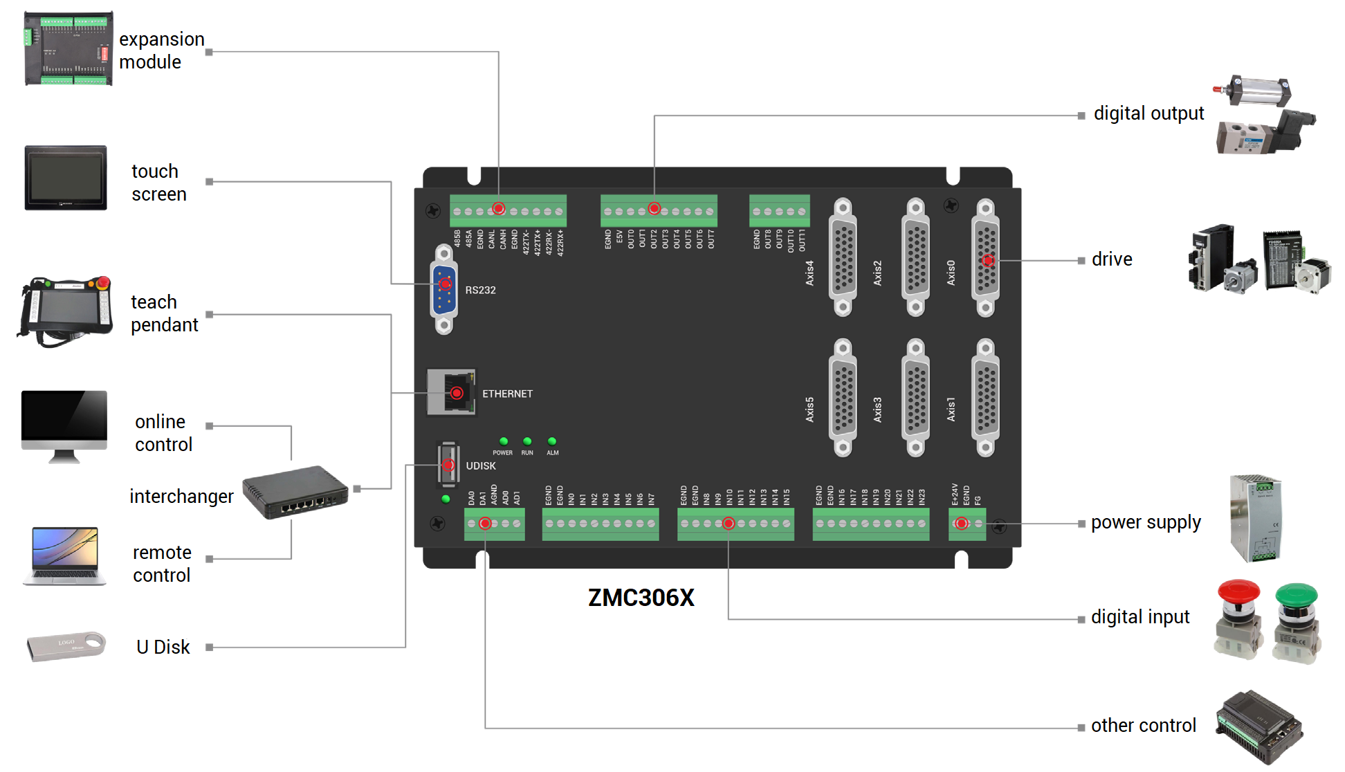
(2) Hardware Wiring
Take pulse type ZMC306X controller as the example, if you need bus type controller, please select controller with EtherCAT interface.
a. main power supply: connect E+24V of controller main power to 24V DC positive pole, and connect EGND to negative pole.
b. Ethernet: use one net cable to connect controller EtherNET to PC ethernet.
c. wiring between driver and controller: connect pulse type driver to controller pulse axis interface
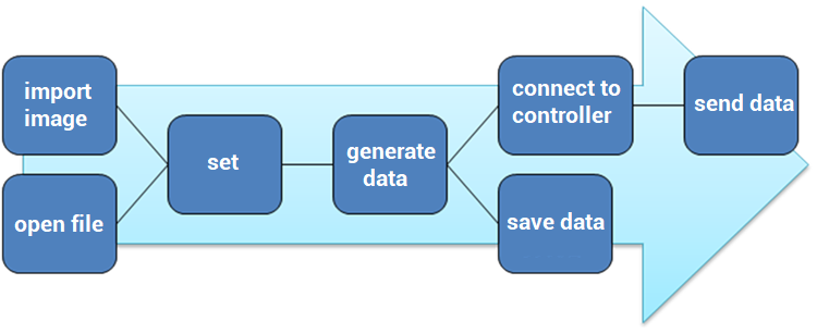
2. How to Map
(1) Basic Steps
Firstly, download CAD mapping software from Zmotion official website or contact us. Then, import graphics whose forms are .dxf, .plt, .aior open files that are .zmo file generated by mapping software, now software will automatically generate processing data. If the effect doesn't meet your requirements, you could refresh the data after customized, and the data will be generated again according to your customized configuration, then you could send data to controller directly or save them into disk for other applications until the data achieves the need.
At the same time, you could connect controller to ZDevelop, then watch situation in ZDevelop.
But please note it can't change the image in ZDevelop.
(2) How To Import Graphic File
In "File" menu, select "import", open import dialog to import graphic files. It supports three formats, they are .dxf file, .plt file, and .ai file.
a. dxf file
If the imported file is .dxf file, software will sort image data automatically, after sorting, processing image will be generated automatically in image interface. If you are not satisfied it, you could manually sort it again through custom motion trajectory function.
b. plt file
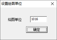
If the imported file is .plt file, you need to select drawing unit firstly, the default is 1016, then software will generate image automatically according to drawing unit.
c. ai file
If the imported file is .ai file, software will automatically convert file's data into mm unit, then generate image automatically.
Please see below image, the blue line is the trajectory to be processed, the green line means empty motion, arrow means the processing direction, and the middle cross means origin position.
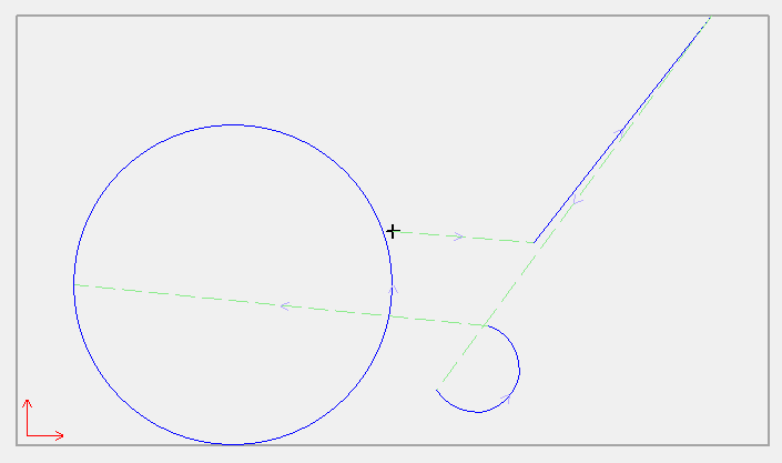
Note: one importing operation imports only one file, if you need to import multiple files, several import operations are needed, then generated images are shown in superposition method.
(3) How To Open File
After importing above format file and editing, if you want to save edited information, the saved format is .zmo form.
zmo format is developed by Zmotion, which is specialized for describing motion trajectory and motion property, and absolute motion is default. And this format not only saves the trajectory, but also saves user configuration. It stores in the object and property method, and there are all kinds of properties in object, property describes object, then user can edit manually.
(4) How to Adjust Manually
After importing file, system will calculate graphic automatically according to algorithm to obtain processing trajectory codes and processing sequence. Then you could select whether modify it manually.
a. set parameters
In menu "Configure", open "parameter setting" window, parameters can be customized now.
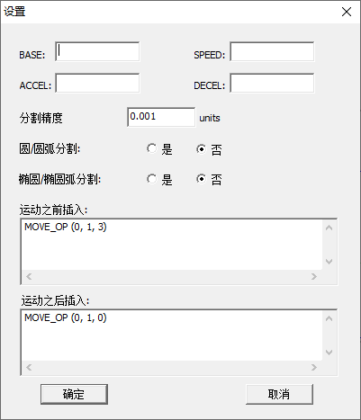
It can be seen it supports global parameters BASE, SPEED, ACCEL, DECEL, and it can assign axis No., axis processing speed, etc.
In addition, you could set segmentation precision, 0 means not to segment, that is, system default data is used. And you could select which type to be segmented, circle or arc or ellipse or ellipse arc.
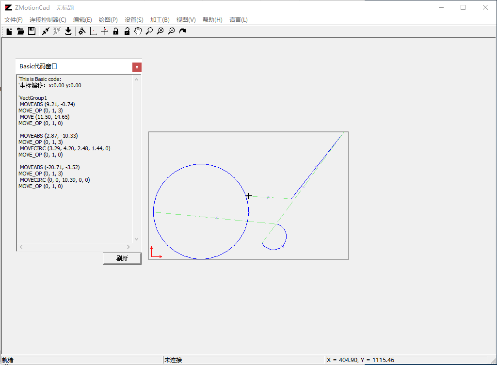
--"no"--
It means not to segment, all circles / arc or ellipse / ellipse arc are not segmented--
For example, image is not segmented, the trajectory of circle is obtained by one arc command.
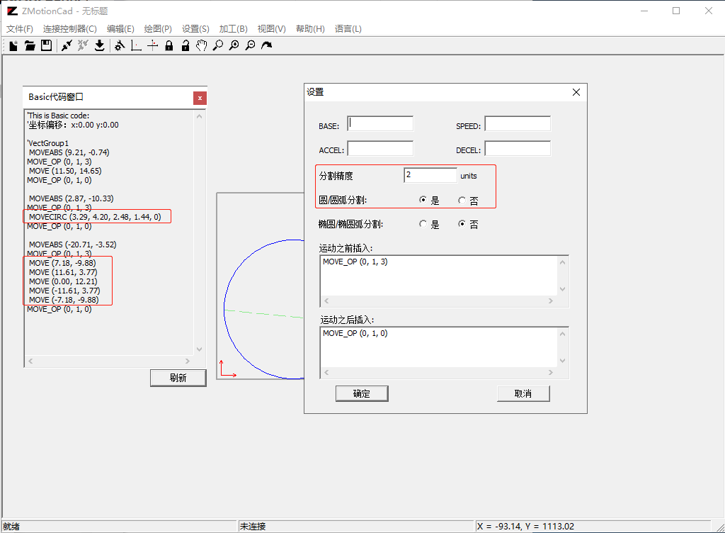
--"yes"--
It means segment the arc into several line segments, the precision is set by yourself, if the precision is bigger than half radius of one certain circle or arc, then this image will not be segmented, if the precision is bigger than minor axis of one certain ellipse or ellipse arc, also it will not be segmented.
For example, the below shows arc segment settings, the precision is 2units, it is more than circle 1/2 radius, the small circle is not segmented, and large circle is segmented as 5 straight lines.
-- "insert before motion"--
It means the content is inserted after one certain motion and before actual axis, the default content is "MOVE_OP (0,1,3)".
--"insert after motion"--
It means the content is inserted after one certain motion and after actual axis, which means the next graphic is the empty motion or has finished, and the default content is "MOVE_OP (0,1,1)".
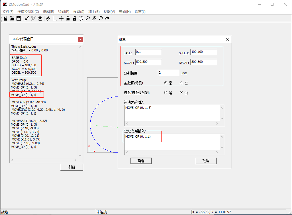
(note, above image is before setting, this image is after setting)
b. set origin
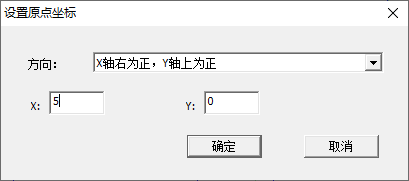
Origin is the processing starting point, which can be customized. And generated Basic code and Bin data change with origin.
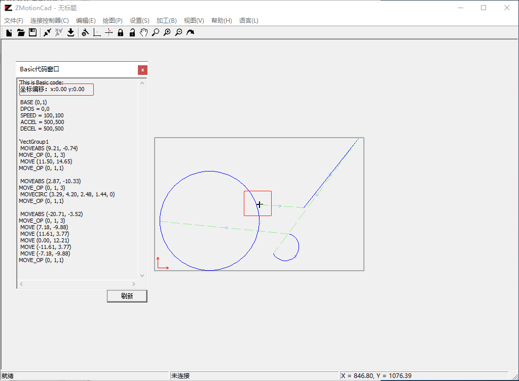
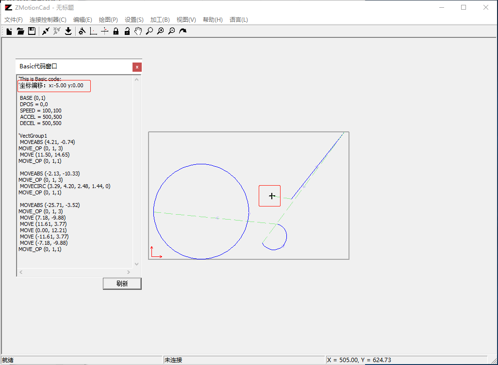
In menu "Setting / Configure", open "configure origin coordinate" window, the default XY coordinates are 0. First to select positive direction for axis X and axis Y, then set origin offset, after this, absolute position of all command parameters will change.
Initial state: origin is (0, 0)
Origin is offset as (5, 0)
c. custom motion trajectory
To begin with, import the file (dxf here), then system automatically sorts processing sequence according to algorithm. Also, if you feel that's not ideal, please manually modify it.
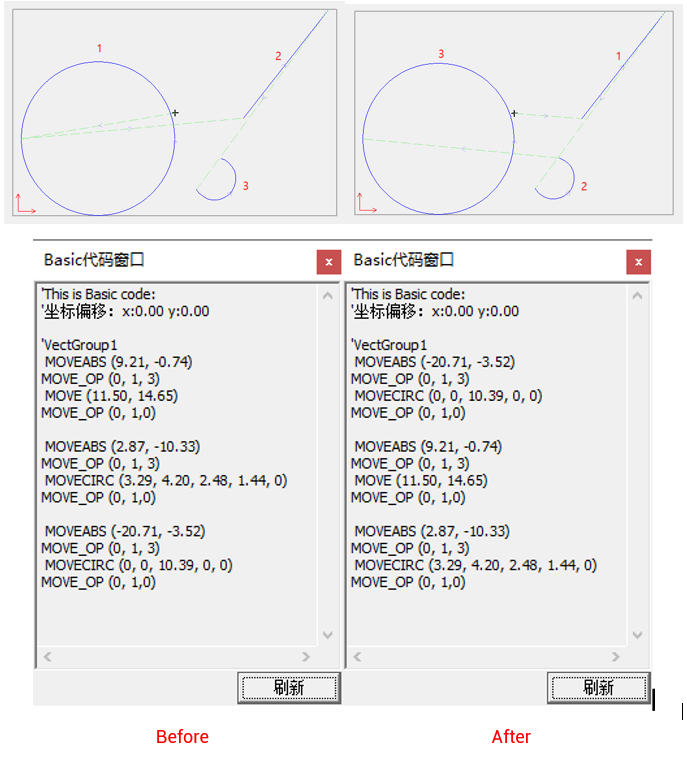
In menu, open "custom" window, and it will number automatically according to processing sequence, the initial default line corresponds to No.1, small circle corresponds to No.2, large circle corresponds to No.3., then you could custom processing sequence through modifying No. sequence.
If current layer data is not image data of dxf file, sorting is not valid, and the No. in sorting window becomes blank.
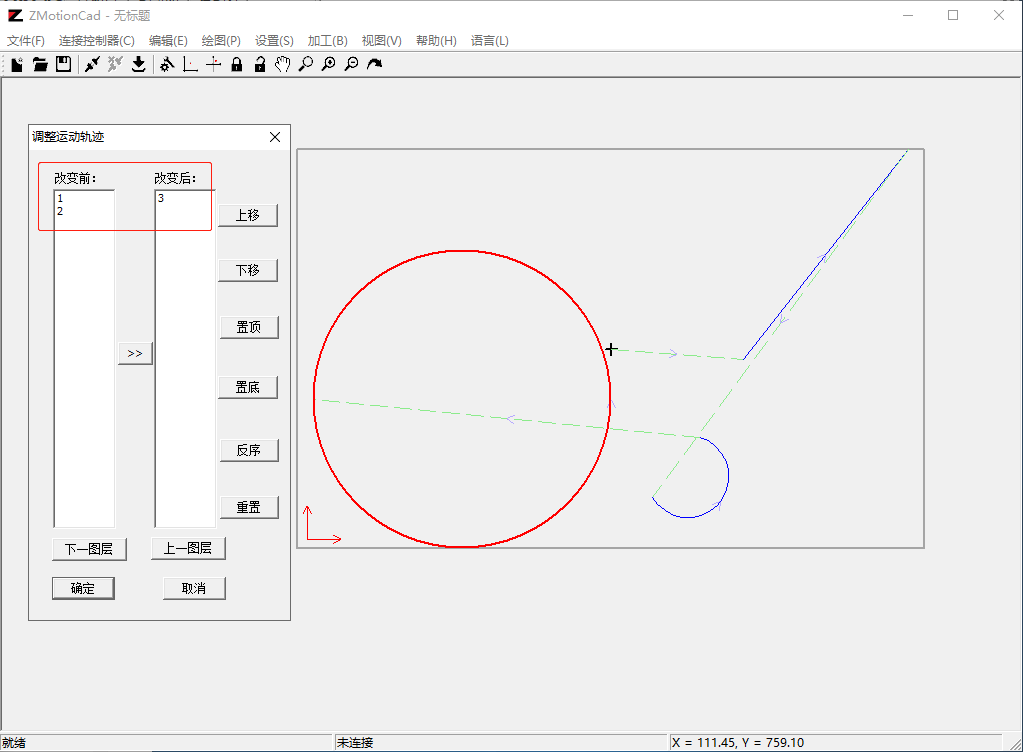
--how to adjust customized trajectory--
Click the No. of edit frame before changing, corresponding line segment will become red. If you double-click it, which means you want to change the sequence of this image, and this mark will move to edit frame after changing. ">>" button represents order of all graphics are to be edited again. After changed, you could select one graphic to do operations of up and down, top and bottom in edit frame, also, "reverse order" button is used to invert graphics' sequence. In addition, "reset" button can edit motion sequence again, then click "OK", at this time, system will sort them from up to down for edit frame after changing and before changing.
For example:
(5) How To Generate Data
After importing image or opening zmo file in mapping software, it will generate processing data required by motion controller according to file data and user configuration. Then you can view generated data from these three windows in "view" window.
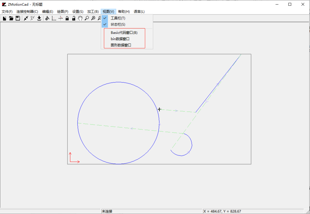
Therefore, data can be generated in the form of Basic code, bin data, image data.
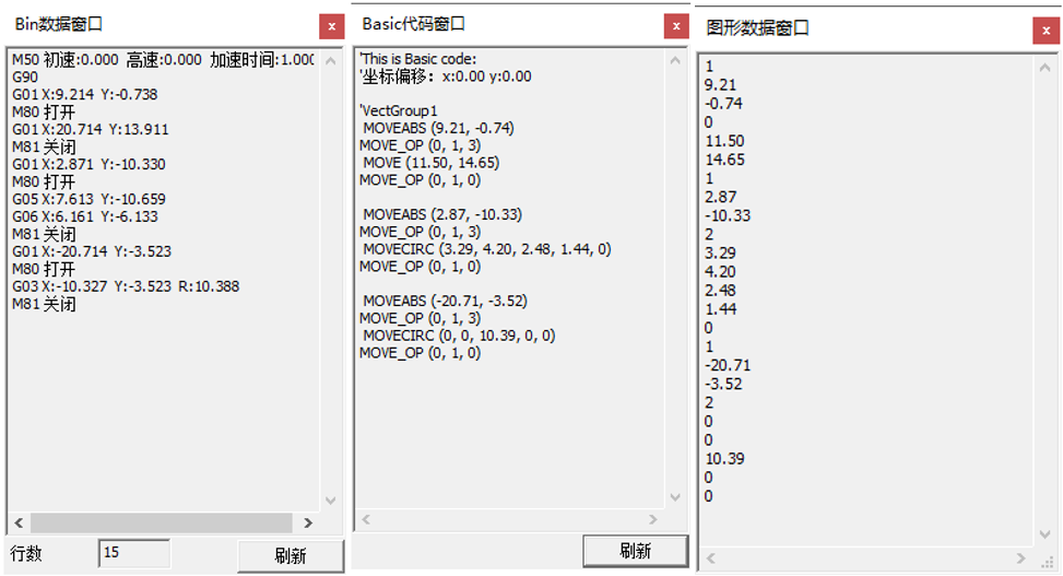
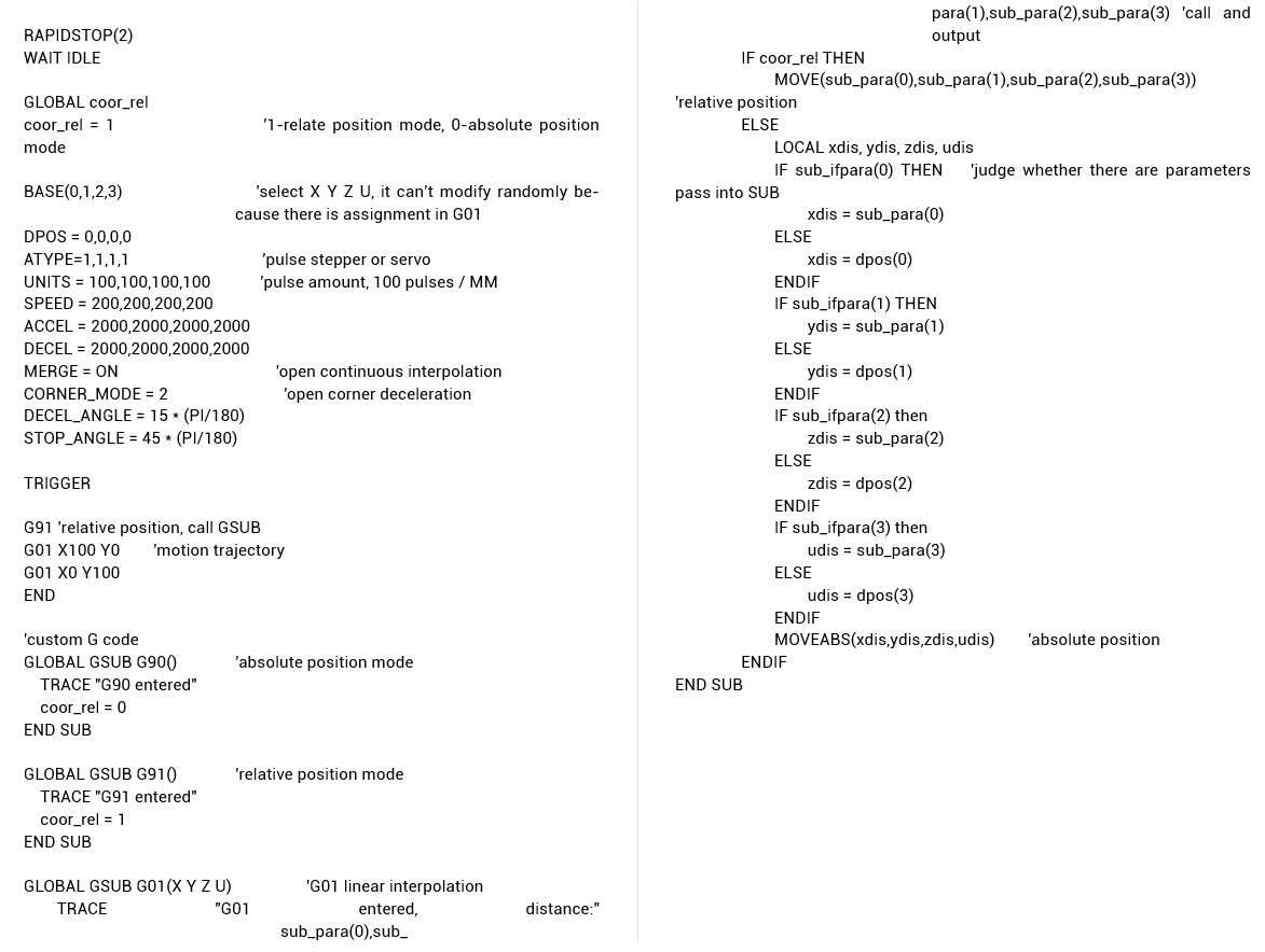
What's more, bin data window data is represented by G code format, when downloading into controller, it needs to use GSUB command to custom G code subfunction. That is, use basic command to custom G code function in GSUB, then call GSUB to execute through G code.
Grammar:
GSUB label([char1] [,char2]…)
…
END SUB
For example:
(6) How To Save Data
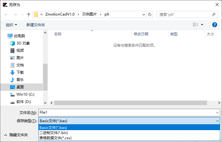
Generated data can be exported and saved, and three types of data can be saved. They are Basic file, binary system and form data file.
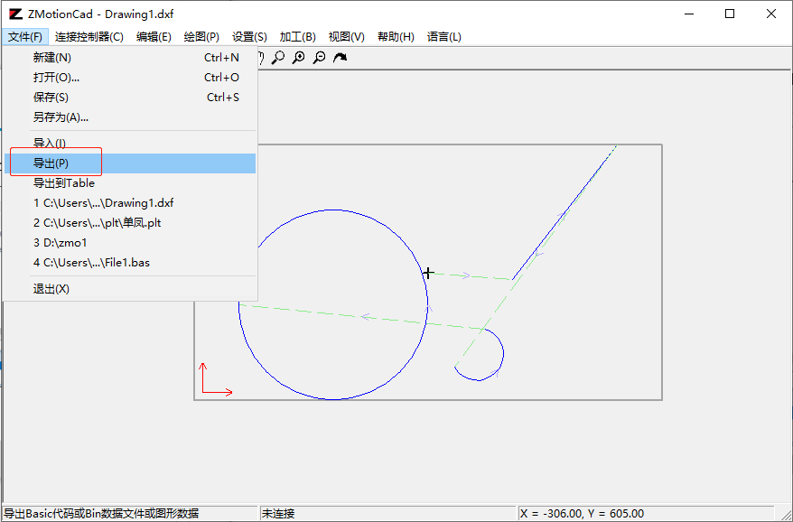
And actually they relate to Basic code window, bin data window and image data window.
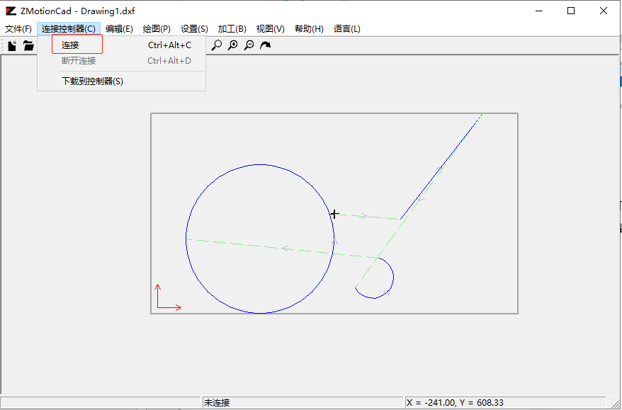
(7) How To Connect To Controller
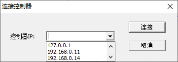
Click "connect" -- "connect to controller", valid controller IP can be obtained automatically, and then select correct IP in drop-down list.
When there is no controller, simulator can be used.
Open simulator that is in directory of ZDevelop, and select IP address 127.0.0.01 to connect.
(8) How To Send Data
The condition of sending data is do connection firstly, controller or simulator. Then, open "download into controller" window, send it to controller in zar, or z3p, or bin method.
a. zar
For zar method, it is necessary to save Basic file into local disk (in the same one directory, automatically generate zar file), then system automatically downloads it into controller and run it directly.
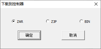
--select zar method--
--Basic code window pops up--
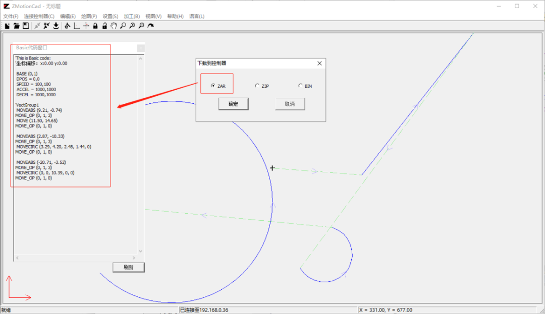
--click "OK"--
--enter file name "BasicFile2. zar" for zar file to be saved in "save as" window, and click "save"--
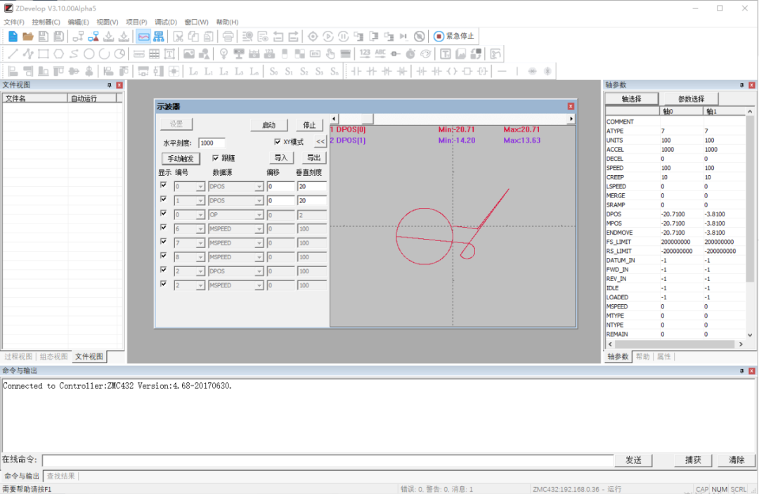
--download into controller to run in zar way--
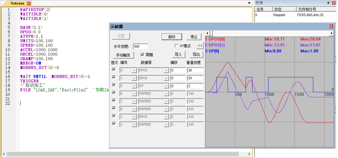
--open oscilloscope to capture motion waveform (Before downloading, set parameters well because zar file doesn't show codes)--
--or: copy basic window code into ZDevelop, it is the same effect with above method --
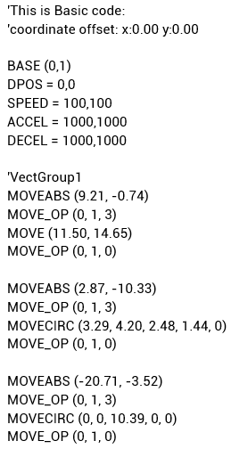
Note: the data sent by mapping software only includes basic axis parameters and motion trajectory, then you need to edit other program in ZDvelop, and run file command to load zar file, in this way, it is time to process.
Calling grammar: FILE "LOAD_ZAR","BasicFile2" 'download zar file into controller from U disk
Called zar file codes:
b. z3p
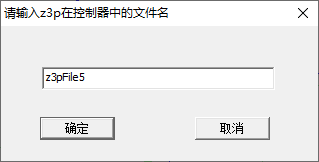
For z3p method, it also needs to save z3p file into local disk firstly, then enter program into controller name, the file will be saved as "z3pFile5. z3p" by default, next load z3p file to controller through command or file 3 tool.
Save z3p file into U disk, then use "FILE3_RUN" command as the task to call z3p file tu run.
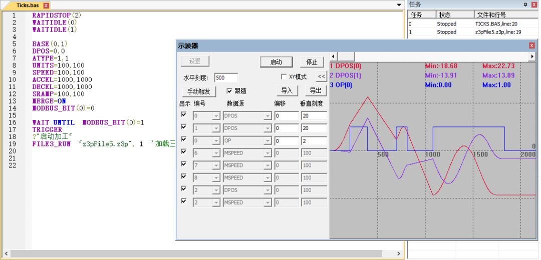
Calling grammar: FILE3_RUN "z3pFile5.z3p", 1 'load file 3 as task No.1
c. bin
For bin method, input Flask block No. that receives the bin data, then system sends bin data to controller Flash according to entered Flash block No. automatically.
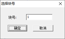
Note: if there is no controller connection currently, or now it is processing under simulation, it can't send into controller.
It also can copy codes from "Basic code window" and download them into controller, it is easy to observe, edit and modify because the program can be viewed in ZDevelop.
3. More Functions
(1) Simulation Processing
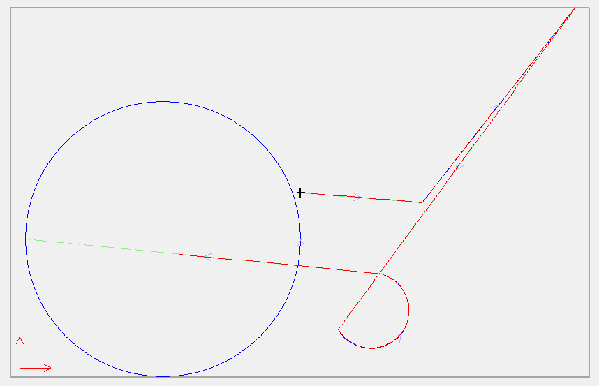
In this CAD mapping software, it can simulate program processing. That is, use visible speed to simulate the process of routine generation. Please refer to below image, use red line to process. During processing, it will lock image and importing, exporting are not allowed, and window size and position can't be changed. If you want to exit simulation, press "Esc" "unlock" or "redraw" buttons.
(2) Multi-File Importing
As it is mentioned above, one importing operation only supports one file. Then, if you need to import several files, corresponding importing times is needed. And generated images are shown in superposition method, when processing, all data will be processed according to sequence.
For example, 2 layers are imported, all are shown by default.
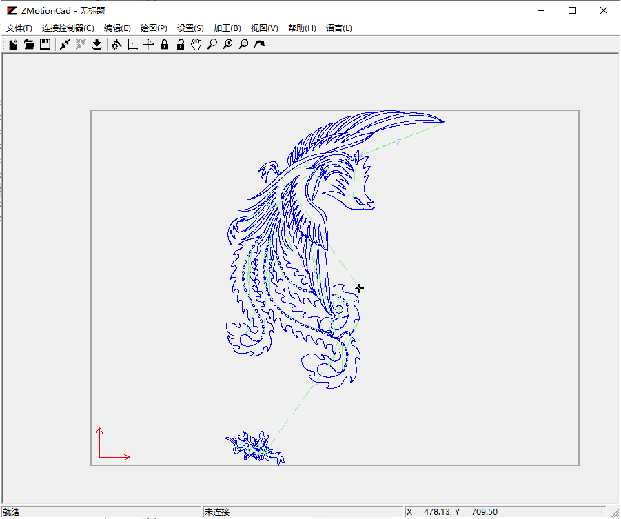
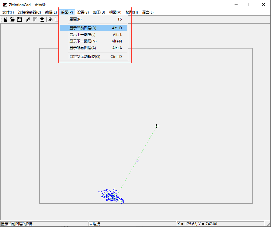
If you want to switch them, select "draw", there are four choices about showing,show current, show former, show next, show all.
ABOUT ZMOTION
That's all, thank you for your reading -- How To Use Zmotion CAD Mapping Software with Motion Controller
For more information, please pay close attention to "Support" and "Download" , and there are other platforms about Zmotion - Youtube & LinkedIn & Twitter & Tiktok & Facebook, including technical information (development environment, routine code), product showing, company development, etc.
Hope to meet you, talk with you and be friends with you. Welcome!
This article is edited by ZMOTION, here, share with you, let's learn together.
ZMOTION: DO THE BEST TO USE MOTION CONTROL.
Note: Copyright belongs to Zmotion Technology, if there is reproduction, please indicate article source. Thank you.
Zmotion Technology focuses on development of motion control technology and general motion control products, it is a national high and new technology enterprise. Due to its concentration and hard work in motion control technology, ZMOTION already become one of the fastest growing industrial motion control companies in China, and is also the rare company who has managed core technologies of motion control and real time industrial control software completely. Here, Zmotion provides motion controller, motion control card, vision motion controller, expansion module and HMI. In addition, there is one program software developed by Zmotion -- ZDevelop. It is a good choice for you to program and compile. And program through upper computer, there is PC manual.